HTAN est l'un des principaux fabricants de charnières, de poignées et de loquets industriels en Chine.


A pull handle can look like the simplest part on an industrial door. It is not. A gasket can make a light enclosure difficult to break open. A recessed grip can preserve the machine envelope but leave too little room for a gloved hand. A rigid stainless bar may remain undamaged while its mounting feet wrinkle the sheet metal around them. The catalog shape fits; the installed assembly still fails.
An industrial pull handle is a fixed or deployable grip used to move an equipment door, drawer, panel, or cover after any retaining mechanism has been released. Industrial pull handle selection should therefore begin before the model number. First identify what the operator moves, the direction and level of effort, the space available for the hand and handle, and the structure that receives the load. Those inputs normally narrow the choice to a fixed raised handle, a recessed handle, or a folding handle. Material, finish, mounting details, and individual dimensions come after that architectural decision.
Règle de sélection : choose the handle architecture from the installed task, not from appearance or material. A model comparison is useful only after the door motion, grip envelope, projection limit, load path, and environment are defined.
Start With the Job, Not the Catalog Shape
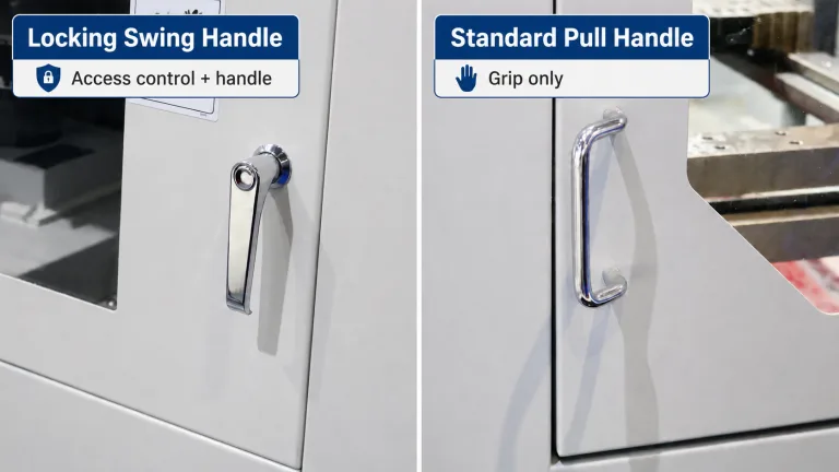
The word “handle” covers parts that do different jobs. A fixed pull handle gives the hand a stationary grip. It does not retain the door. A swing handle may rotate a cam or drive a multi-point rod lock. A folding carrying handle may support the mass of a portable case. A lift handle on a cover may be exposed to gravity, impact, and an off-center load. These parts can look related in a product gallery, but their load paths and approval questions are different.
For these applications, the handle gives the operator a grip for opening, closing, pushing, pulling, or controlling the movement of an industrial door, drawer, panel, or access cover. A folding version remains a pull handle when the folding action only reduces projection. If the part must carry the complete enclosure, actuate a latch, restrict access, or serve as a certified lifting point, stop treating it as a generic pull handle. The functional requirement has changed.
- Open or close a door: determine breakaway force, pull direction, hinge leverage, and hand clearance.
- Move a sliding panel or drawer: determine travel direction, rail friction, skew sensitivity, and clearance through the full stroke.
- Raise a cover: determine cover weight, center of gravity, hinge axis, opening angle, and whether the handle is used only during motion.
- Carry equipment: specify a carrying handle and validate the complete case, mounting joint, dynamic loading, and load sharing. Do not inherit approval from a door-pull application.
The Motion Sets the Force Direction
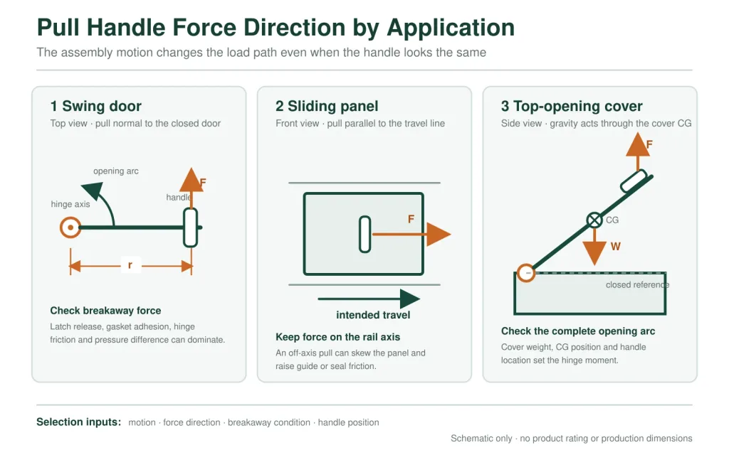
Door weight alone does not tell you the force at a pull handle. A vertical swing door is supported by its hinges, so the operator is usually overcoming latch release, gasket adhesion, hinge friction, pressure difference, and acceleration—not lifting the full door mass. A horizontal cover is different because gravity creates a moment about the hinge. A sliding panel introduces rail friction and can bind if the operator pulls away from the intended travel line.
For a swing door, the first-order relationship is M = F × r, où M is the resisting moment about the hinge axis, F is the hand force, and r is the perpendicular distance from the hinge axis to the line of action. This is a general statics relationship, not a product rating. Moving the handle farther from the hinge can reduce required hand force, but only if the panel edge, latch arrangement, and operator approach permit it.
| Assembly | Dominant force input | What can mislead selection |
|---|---|---|
| Swing door | Breakaway force and hinge moment | Using door mass as the handle load |
| Sliding door or drawer | Rail friction, seal drag, and skew | Testing only a centered pull on an unloaded slide |
| Horizontal cover | Weight and center-of-gravity moment | Ignoring how force changes through the opening arc |
| Sealed enclosure | Gasket adhesion or compression release | Measuring effort only after the seal has already broken free |
| Portable case | Supported mass plus motion and impact | Using a door-pull handle rating as a carrying rating |
Three Pull-Handle Architectures
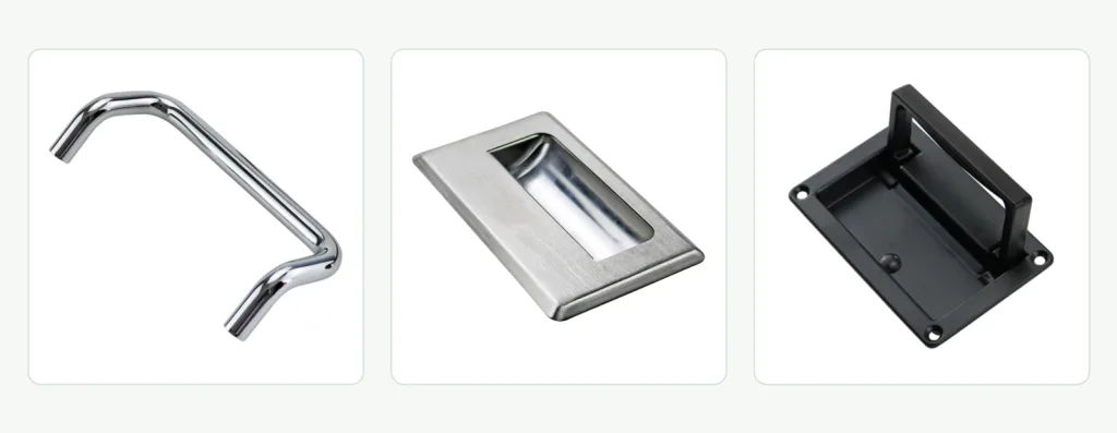
Most early selections can be organized around three architectures. A fixed raised handle keeps the grip permanently available. A recessed handle moves the grip into the panel envelope. A folding handle provides a raised grip when needed and a lower profile when stowed. The right starting point is the constraint that cannot be negotiated—not the option with the longest list of advantages.
| Dominant requirement | Start with | Trade-off that still needs review |
|---|---|---|
| Immediate full-hand access and a simple rigid load path | Fixed raised pull handle | Permanent projection, impact, and snag exposure |
| A flush or nearly flush exterior envelope | Poignée de tirage encastrée | Panel cutout, grip depth, drainage, and reduced leverage |
| Full grip during use but low projection during transport or storage | Folding pull handle | Pivot wear, stowed retention, rattle, pinch points, and contamination |
| Gloved operation or repeated opening of a resisting door | Fixed U-shaped or tubular handle | Grip clearance, projection, foot spacing, and panel reinforcement |
| The complete enclosure must be carried | Load-rated carrying-handle system | Dynamic load, attachment strength, balance, and possible two-handle load sharing |
| The handle must rotate a cam or rod mechanism | Operating handle or latch system | Mechanism travel, keeper engagement, access control, and interlocking |
What Each Architecture Adds to the Assembly
A fixed raised handle has the shortest and most visible load path: grip, legs, feet, fasteners, panel. Its lack of a moving joint removes pivot wear and stowed-position problems, but it does not remove panel bending or fastener movement. Rigid handles can also be less tolerant of mounting surfaces that are not coplanar. Tightening both feet onto a bowed panel may preload the handle or pull the panel out of shape before an operator touches it.
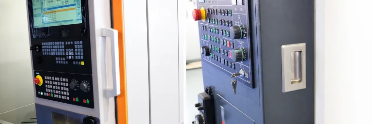
A recessed handle trades exterior projection for panel integration. The pocket or cutout removes material from the panel and can interrupt a formed stiffening feature. The surrounding flange must seat correctly, and the hand must enter the recess without striking an edge. Water, chips, dust, or cleaning residue can collect in the pocket if its orientation and drainage are not considered. A flush face is therefore an assembly result, not simply a product feature.
A folding handle adds a deployed load path and a stowed state. When deployed, the bail or grip transfers force through pivots, stops, brackets, and the mounting base. When stowed, a spring, detent, friction feature, or gravity may control its position. The design must make clear what carries the operating load: the pivot pin, a positive stop, contact between the grip and base, or a combination. A handle that folds neatly in a photograph can still rattle, pinch, jam with debris, or overload a small pivot under an angled pull.
If the profile decision is unresolved, compare surface-mount and recessed handles before selecting a model.
When a raised grip is acceptable only during operation, use the fixed-versus-folding handle comparison to review permanent projection, pivot wear, retention, and the moving-joint load path.
Grip Is a Working Envelope
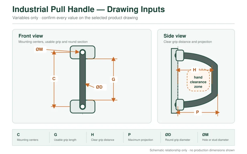
Overall length is a poor proxy for usability. The operator touches only part of the handle, and the hand occupies space that catalog photographs do not show. A useful drawing should separate mounting centers C, usable grip length G, clear grip distance H, maximum projection P, grip diameter or section, foot size, and the surrounding keep-out area.
G must fit the intended hand position rather than merely look proportional to the door. H must accommodate fingers, gloves, and the actual approach angle. P controls both hand access and collision risk. A larger grip can improve control but also move the hand into a frame, latch, cable, adjacent panel, or traffic path. These attributes should be read together because increasing one can make another worse.
Edge shape matters as well. A broad, smooth contact surface generally distributes hand pressure better than a narrow section, while sharp transitions, exposed threads, or unfinished cutout edges create local discomfort. No universal grip size applies because glove thickness, required force, operating frequency, hand approach, and model geometry vary by project. Dimensions come from the supplier drawing; usability is confirmed on the representative assembly.
Projection Belongs to the Machine Layout
A fixed handle does not stop occupying space when nobody is using it. Its projection remains part of the machine envelope during operation, service, packing, transport, and storage. A handle that is safe on the front of a freestanding cabinet may become an impact point beside a walkway, a snag point near clothing or cables, or an interference point when two doors open toward one another.
Review the handle in at least three states: the door closed, the door moving, and the door fully open. Nearby guards, rails, adjacent equipment, removable panels, carts, and service tools may enter the same space at different times. For folding handles, include both the stowed envelope and the swept path as the grip rises. For recessed handles, include the hand itself; a flush outer face does not guarantee that fingers have a usable approach.
A low-profile handle can solve a clearance problem and create an operating problem. If the operator cannot insert a gloved hand or generate the required pull without fingertip loading, the exterior envelope is clean but the access task is not complete.
The Handle May Pass While the Panel Fails
A pull handle transfers hand force through its grip, legs or pivots, mounting feet, fasteners, panel skin, and any backing structure. The weakest point may be nowhere near the grip. Thin sheet can dome under a handle foot, holes can elongate, inserts can rotate, nuts can loosen, and a painted surface can crack around a moving joint. None of those failures require the handle body to break.
A catalog load value is meaningful only with its direction, fixture, mounting hardware, load application point, duration or cycling, and acceptance criterion. A straight pull on a rigid test plate does not establish capacity for an angled pull on a wide door skin. Nor does a stainless material callout prove that the joint can carry more load. The assembly rating can be controlled by panel stiffness or fastener pull-through before the handle reaches its own limit.
Read a Load Value With Its Boundary Conditions
A useful supplier value should identify the tested model and define where and how force entered the grip. A force applied at the center of a bar distributes load differently from a force applied near one leg. Tension normal to the panel, shear parallel to the panel, and an oblique pull create different reactions at the feet and fasteners. If only one direction was tested, do not silently extend the result to the others.
The fixture matters just as much. Record the plate material and thickness, hole geometry, backing hardware, fastener type, tightening condition, and unsupported span. Then identify whether the result describes a one-time proof load, a working-load recommendation, an impact event, or repeated cycles. Finally, define failure: fracture, permanent deformation, specified deflection, loosened hardware, loss of function, or visible panel damage. Without these conditions, a number may help compare catalog entries but cannot approve the installed door.
Illustrative engineering scenario: a fixed handle remains intact during a rigid-fixture pull test, then wrinkles the production door around one foot because the operator pulls at an angle and the sheet has no local reinforcement. The nominal handle is not defective. The load path was incomplete. This is an illustrative scenario, not a customer project record or product test claim.
Where force is significant or repeated, carry it into a formed flange, internal bracket, backing plate, frame member, or another deliberate reinforcement. The correct feature depends on the panel material and geometry. Simply adding a larger handle can increase the moment on the same weak sheet.
Mounting Centers Are Not the Joint
Two models with the same center-to-center dimension are not automatically interchangeable. The feet may have different widths, contact areas, stud lengths, thread sizes, hole requirements, edge distances, or access needs. One model may use front screws into threaded handle legs. Another may place studs on the handle and require nuts behind the panel. A third may rely on panel-fixed studs or inserts. Each arrangement changes assembly access and service behavior.
A clean front does not prove one-sided installation: hidden handle studs can still require rear access for nuts. Compare front screws, through-bolts, rear-mounted studs, threaded inserts, and weld-on joints in the industrial pull handle mounting methods guide.
Tolerance Across Two Mounting Feet
A two-foot handle asks several features to agree at once: the handle’s mounting centers, hole positions, foot faces, panel flatness, coating thickness, and the location of any studs, inserts, or backing plate. Each feature can be within its own tolerance while the assembled pair still resists seating. A rigid handle does not bend politely to correct a large positional error. Tightening the fasteners may instead pull one foot sideways, tilt an insert, scrape the coating, or leave residual stress in the panel.
Slots and oversized holes can create assembly freedom, but they also reduce positive location and may allow movement under alternating push-pull loads. A floating nut or compliant gasket can accommodate some variation, yet neither should be used to hide an uncontrolled hole pattern. The drawing should state the datum scheme and the intended adjustment feature, while the sample build should show that both feet seat without forcing the handle into position.
- Mounting centers and hole or stud diameter
- Foot dimensions and contact area
- Panel material, thickness, coating, and reinforcement
- Front and rear assembly access
- Fastener type, thread engagement, washers, and retention method
- Clearance to internal components, wiring, seals, and door flanges
Le matériau suit l'exposition
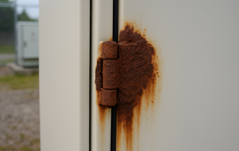
Material should narrow a mechanically suitable architecture; it should not rescue an unsuitable one. Stainless steel can offer useful corrosion resistance, but a stainless bar with incompatible fasteners, contaminated surfaces, or water-holding crevices can still develop corrosion. Aluminum reduces mass but introduces its own strength, finish, and mixed-metal questions. Engineering polymers avoid red rust and may provide electrical or thermal benefits, yet resin grade, reinforcement, temperature, UV exposure, chemicals, and inserts all affect performance.
Describe the real exposure instead of writing “outdoor” or “corrosion resistant” alone. Rain, coastal chlorides, road salt, alkaline washdown, acidic fumes, disinfectants, oils, sunlight, and freeze-thaw cycles attack different parts of the assembly. Cleaning chemistry can be more severe than normal service. The specification should identify the handle body, moving parts, fasteners, washers, inserts, coating, and any gasket—not just the visible grip.
Surface finish is both functional and visual. Roughness, directional grain, polishing quality, coating edges, and casting texture affect cleanability, grip feel, appearance, and the visibility of wear. A finish name does not establish corrosion performance or cleaning compatibility. When exposure matters, request the exact material and finish for the selected model and define the project-specific evidence required for approval.
Placement Changes Operator Effort
Handle location is part of the mechanism even though the handle itself does not move. On a swing door, increasing distance from the hinge generally increases leverage. Placing the grip too close to the free edge can improve leverage but crowd the frame, latch, or pinch zone. On a sliding door, the grip should support force close to the travel direction; an off-axis pull can increase guide or rail binding. On a cover, handle location relative to the center of gravity changes how the cover feels as it starts to rise.
Orientation matters too. A vertical grip, horizontal grip, and angled grip can present the same usable length on a drawing while producing different wrist positions and pull directions. The best orientation depends on operator position, opening direction, frequency, gloves, nearby obstructions, and whether the same handle is used to push the panel closed.
Two handles do not guarantee equal load sharing. Operators rarely apply identical force at the same time, and a flexible cover can twist between mounting points. If the task genuinely requires two-person lifting or controlled movement of a wide panel, define the expected use and validate the panel with realistic asymmetric loading. Do not divide the total load by two and treat the result as an automatic rating for each handle.
A Representative Door Settles the Choice
A product sample proves very little when it is held in the hand. Mount it on a representative door or panel with the intended holes, fasteners, coating stack, reinforcement, seal, hinge, latch, and nearby hardware. The objective is not to create a universal laboratory protocol. It is to expose assembly conflicts before the production drawing is released.
- Release the latch completely, then observe the initial breakaway effort and pull direction.
- Operate the door with the intended bare or gloved hand approach. Watch the frame, door edge, and adjacent hardware for pinch or contact.
- Move through the complete door travel. Include the folded and deployed envelopes when the handle has a moving grip.
- Apply realistic pull directions, including the off-axis component expected from operator position. Look for panel oil-canning, foot movement, insert rotation, fastener loosening, or coating damage.
- Inspect rear clearance and service access with the internal equipment installed. A nut that is reachable on an empty shell may be blocked in the finished cabinet.
- Where sealing or cleaning matters, inspect the mounting penetrations, water paths, recesses, and residue traps as part of the enclosure—not as a claim made by the handle alone.
Record what was tested and what was not. A fit check does not establish fatigue life. A short pull test does not establish a carrying rating. A visible stainless finish does not confirm grade. These boundaries make the sample review more useful, not less.
Inputs That Separate Candidate Models
Once the architecture is settled, model selection becomes much faster. A supplier does not need a large generic specification package; it needs the few assembly facts that eliminate the wrong families. Send the following with the inquiry:
- Door, drawer, panel, cover, or portable-case function
- Motion direction and the expected operator pull direction
- Measured or project-defined opening force, or the load case if it is a carrying application
- Available grip length, hand clearance, projection limit, and mounting zone
- Panel material, thickness, reinforcement, coating, and rear access
- Rain, washdown, chlorides, chemicals, UV, temperature, or hygiene constraints
- Door drawing and photographs of both sides of the proposed mounting area
- Required supplier evidence, such as a controlled drawing, material declaration, finish description, or model-specific test information
With these inputs defined, use the gamme de poignées de traction industrielles to compare available families and then confirm model-specific dimensions, materials, options, and drawing data.
Send the Door Conditions, Not Just a Handle Photo
Share the door or cover drawing, motion, pull direction, mounting zone, panel stack, environment, and any grip or projection limit. HTAN can use those inputs to identify which available pull-handle family should be reviewed and which model-specific drawing data still need confirmation.
FAQ About Industrial Pull Handle Selection
What is an industrial pull handle?
An industrial pull handle is a stationary or deployable grip used to open, close, push, pull, or control an equipment door, drawer, panel, or cover. It is not automatically a latch, lock, operating handle, carrying handle, or lifting point. The product function and load case must be named before model selection.
How do I choose between a fixed, recessed, and folding pull handle?
Start with the dominant space and operating constraint. A fixed raised handle provides immediate full-hand access and a simple rigid load path. A recessed handle minimizes exterior projection but requires a panel cutout and usually provides less grip depth. A folding handle combines a raised grip with a lower stowed profile, but its pivots, retention, pinch points, and contamination exposure require review.
Can an industrial pull handle be used to lift or carry the complete enclosure?
Not unless the lifting or carrying function is explicitly designed and documented for the complete assembly. Door-opening force and carrying load are different load cases. A carrying application must address supported mass, dynamic effects, handle attachment, panel or case strength, balance, load direction, and any two-handle load sharing.
Which pull handle dimensions matter most?
Use mounting centers, usable grip length, clear grip distance, maximum projection, grip diameter or section, foot size, and hole or stud dimensions. Also define the keep-out space for the hand, nearby frame, latch, internal hardware, and the handle’s full swept path if it folds.
How is industrial pull handle load capacity specified?
Use a model-specific value that identifies load direction, application point, fixture, mounting hardware, duration or cycling, and the acceptance criterion. Do not infer capacity from material, bar diameter, mounting centers, or heavy-duty wording. The installed limit may be controlled by the panel, fasteners, inserts, or reinforcement before the handle body.
What is the best industrial pull handle material for outdoor equipment?
There is no universal best material. Outdoor exposure may include rain, chlorides, road salt, UV, cleaning chemicals, and temperature cycling. Select a mechanically suitable handle first, then specify the handle body, pivots, inserts, fasteners, finish, and sealing details for the actual exposure. Stainless steel grade alone does not approve the complete joint.