HTAN is one of the leading manufacturers of industrial hinges, handles and latches in China.


An adjustable torque hinge is not simply a standard hinge with a screw added to it. The adjustment changes an internal force or friction condition that changes the hinge’s resisting torque within a designed working range. The useful engineering question is therefore not “Can it be tightened?” but “What does the adjuster change, how much usable torque range does that create, and where does adjustment stop being a valid correction?”
This page explains the adjustable torque hinge as a mechanism: the adjustment interface, preload path, friction torque, usable adjustment range, position-holding behavior, and adjustment limits. It does not try to replace a full torque-hinge selection guide or a model-specific datasheet.
If the project is still deciding between fixed torque, adjustable torque, one-way torque, detent, spring, or another hinge family, use the torque hinge selection guide for that broader decision.
What Makes an Adjustable Torque Hinge Adjustable?
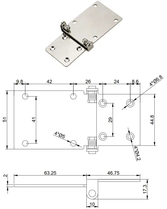
A torque hinge resists rotation through an internal mechanism instead of swinging freely around a pin. In an adjustable version, the manufacturer provides a controlled way to change part of that torque-generating mechanism after assembly or during setup.
In many friction-based designs, the adjuster changes preload on friction elements, washers, discs, sleeves, spring components, or another clamped interface. More preload increases the normal force at the friction surfaces, which can raise the resisting torque within the mechanism’s designed range. Other adjustable torque-hinge constructions can use different internal geometry, so the exact adjustment path must come from the product drawing or supplier data.
The distinction matters because “adjustable” describes a controllable mechanism, not unlimited capacity. The adjustment feature is there to tune the hinge inside a defined envelope. It is not intended to compensate indefinitely for an undersized hinge, a heavier-than-planned panel, poor alignment, loose mounting, or worn internal parts.
Adjustment changes hinge resistance. It does not change the external load. The lid, display, cover, or panel still creates the same gravity moment for a given mass, center of gravity, and angle.
What the Adjustment Changes Inside the Hinge
For a simple friction-stack model, the resisting torque depends on how strongly the friction surfaces are pressed together, the effective friction behavior of the material pair, and the effective radius at which the friction force acts.
Conceptual friction relationship:
Tresist ∝ μ × N × reff
μ represents the effective friction behavior of the interface, N the normal or clamping force created by preload, and reff the effective friction radius. Multiple friction interfaces can add resisting torque, but the exact relationship depends on the hinge construction.
This is a mechanism explanation, not a product-sizing equation. Do not calculate a production hinge from this relationship unless the manufacturer provides the internal geometry and test basis.
The Preload Path Matters
Turning an adjustment screw or nut does not create torque directly. It changes the force path through the internal stack. If the adjuster compresses a spring or clamping element, that force is transferred into the friction surfaces. The friction surfaces then resist relative rotation around the hinge axis.
This is why the adjuster position alone is not a torque measurement. Two hinges can show the same visible screw position while producing different torque if their friction stack, wear state, temperature, manufacturing tolerance, or internal preload condition differs.
More Tightening Is Not Necessarily Linear
A common mistake is to treat screw rotation as if each quarter-turn adds the same amount of torque. That relationship may not be linear. The spring or friction stack can have its own load-deflection behavior, and the contact condition can change as preload rises. Near the end of adjustment travel, additional screw movement may create a large internal force change with little useful gain in controlled hinge behavior.
If torque setting matters in production, use measured hinge torque or a supplier-defined adjustment method. Do not use “number of screw turns from loose” as a universal torque specification unless the product documentation explicitly defines that method.
Adjustment Range Is a Working Window
An adjustable torque hinge should be treated as having a usable adjustment window, not an infinite low-to-high setting. The lower setting must remain inside the supplier-defined adjustment condition, while the upper setting must stay within the mechanical limits of the adjuster and torque-generating mechanism.
| Datasheet Term or Condition | What It Should Mean | What Still Needs Clarification |
|---|---|---|
| Adjustment range | Usable torque window the mechanism is designed to cover | Per hinge or per pair; test direction; angle; temperature; new or conditioned state |
| Minimum setting | Lowest intended torque setting that remains mechanically controlled | Whether the adjuster can be backed off further and whether doing so is allowed |
| Maximum setting | Highest intended torque setting within the design envelope | Mechanical stop, allowable adjuster position, and whether over-tightening can damage the mechanism |
| Torque tolerance | Allowed variation around the specified torque condition | Measurement method, speed, direction, angle, and conditioning |
| Adjustment method | How the supplier intends torque to be changed | Tool, access direction, locking step, and whether field adjustment is permitted |
If a datasheet lists only a broad torque range without the measurement condition, the number is incomplete for engineering use. Holding torque at rest, breakaway torque, and moving torque can differ. Torque can also vary with direction and hinge angle depending on the internal construction.
The useful question is not “How high can I tighten it?” It is “What torque range can this hinge deliver repeatedly while still operating as designed?”
Holding, Breakaway, and Running Torque
A panel can stay in position and still feel poor to operate. If the hinge is adjusted near the upper end of its range, the user may need excessive force to start motion. If the setting is too low, the panel may drift at the most demanding angle even though it feels smooth through the rest of the travel.
Three torque conditions are often worth separating when the application is sensitive to feel:
- Holding torque: resistance available to keep the panel from moving at rest.
- Breakaway torque: torque required to initiate movement from rest.
- Running torque: resisting torque while the hinge is already moving at the defined speed and direction.
A single catalog number may not describe all three. If consistent feel across the motion is important, request the torque measurement method or torque-versus-angle information for the actual hinge rather than assuming that a nominal adjustable range is flat through the entire rotation.
Temperature and cycling can also change friction behavior. That does not make an adjustable hinge unsuitable; it means the adjustment target and acceptance method must match the real operating condition instead of a single bench measurement.
Equal Screw Position Does Not Mean Equal Torque
Using two adjustable torque hinges does not guarantee equal torque sharing. The pair has to rotate around a common axis, sit on compatible mounting surfaces, and be adjusted so one hinge is not doing most of the work.
Equal screw position is not the same as equal hinge torque. One unit may have slightly different internal friction or preload, and the assembly itself may load the hinges unequally. If one hinge is set much higher than the other, the panel can feel sticky, twist during motion, or place extra load into the mounts even when the total holding torque appears adequate.
Consider a lid fitted with two adjustable torque hinges. During assembly, both adjustment screws are turned to the same visible position. The lid still drifts, so the technician tightens only the easier-to-reach hinge until the lid holds. The final assembly now has enough total resistance, but one hinge carries most of the friction torque while the other contributes much less. Operating force rises and the hinge line can feel uneven. The problem was treated as “not enough torque” when the real issue was pair adjustment and assembly condition. This is an illustrative engineering scenario, not a customer project record or product test claim.
For paired hinges, the useful acceptance check is assembly behavior: stable holding at the required angles, acceptable operating force, no binding, and repeatable motion. If individual hinge torque is measured, use the same method and condition for both units.
Where Adjustment Adds Value
Adjustment is useful when the application benefits from controlled tuning rather than a single preset torque. Typical cases include prototype loads that are still changing, several product variants that share one hinge location, operator feel that needs to be tuned during development, or a service procedure that intentionally allows post-installation adjustment.
A fixed-torque hinge can be the cleaner choice when the load and required torque are already stable, repeatability matters more than tuning, or the adjustment point should not be accessible after production. That comparison is only a boundary here. If the project still needs to choose between fixed, adjustable, one-way, detent, or other torque-hinge families, make that decision on the broader torque-hinge selection page.
The key is to treat adjustability as a functional requirement, not as a default upgrade. If the setting will never be revisited and the production torque is already known, the adjuster may add a control step without adding useful performance.
Adjustment Access in the Final Assembly
An adjustable hinge can be correctly specified and still become effectively non-adjustable after installation. A screw that faces a cabinet wall, a cover return, a cable bundle, or another component cannot be used without disassembling the product.
The drawing should show the adjustment tool path, not just the hinge outline. Check whether the required hex key, screwdriver, wrench, or proprietary tool can approach the adjuster through the full assembly. If an access hole is needed, it should be part of the production drawing rather than improvised during assembly.
Installation animation showing the hinge mounting position, fastener access, and assembled orientation.
Also decide when adjustment is allowed. Some products are tuned once during assembly and then left untouched. Others intentionally permit service adjustment. If the setting should not move after tuning, the model may require a locking feature, thread treatment, cap, or another supplier-defined retention method.
For two hinges, tool access should allow both units to be adjusted without forcing the lid or panel into a distorted position. The part should be supported during adjustment if the panel load would otherwise rotate the hinge unexpectedly.
When More Adjustment Is the Wrong Fix
If a previously stable panel begins to drift, tightening the adjuster may restore position temporarily. That does not prove the original setting was wrong. The loss of holding behavior can come from several different changes in the assembly.
Mounting movement
Loose fasteners or a flexible bracket can change the hinge axis and apparent holding behavior.
Panel load changed
Added hardware or a moved center of gravity can increase the external moment beyond the original setting.
Internal wear
Friction surfaces or preload components can change with service, depending on the hinge design and duty.
Misalignment
Two hinges that no longer share a common axis can add binding in one part of the travel and drift in another.
If the adjuster is already near the end of its permitted range, more tightening can hide the symptom while increasing internal stress or operating force. The correct next step is to identify what changed before using the adjustment mechanism as compensation.
Adjustment is a setup and tuning feature. It is not a universal repair method for hinge wear, loose mounting, overloaded panels, or damaged internal components.
Adjustment Data the Datasheet Must Define
An adjustable torque hinge is much easier to compare when the supplier defines the adjustment mechanism and the torque condition instead of publishing only a minimum and maximum number.
- Adjustment range: per hinge or per pair, and the intended usable minimum and maximum.
- Torque definition: holding, breakaway, running, or another supplier-defined measurement.
- Measurement condition: rotation direction, angle, speed, temperature, and whether the hinge is new or conditioned.
- Adjustment interface: screw, nut, tool type, access direction, and any locking step.
- Adjustment limit: mechanical stop, allowed screw position, or another boundary that prevents over-adjustment.
- Rotation envelope: usable angle and any built-in stop or interference limit.
- Directional behavior: whether resisting torque is intended to be similar or different in the two directions.
- Field adjustment: whether post-installation tuning is permitted and how the setting should be retained.
Once these fields are clear, the engineer can compare adjustable mechanisms without turning a definition page into a full sizing exercise. Model dimensions and commercial options belong in the torque hinge product range.
Adjustable Torque Hinge FAQ
Is a variable torque hinge the same as an adjustable torque hinge?
Not necessarily. “Variable torque” can describe a hinge whose resisting torque changes by design, while “adjustable torque” specifically means the product provides a controlled way to change the torque setting within a defined range. The supplier should define how the term is used for the actual model.
Does torque adjustment change the hinge opening angle?
Not necessarily. Torque adjustment changes rotational resistance. The allowable rotation angle or mechanical stop is a separate model-specific feature unless the hinge design intentionally combines those functions.
Can opening and closing torque be adjusted independently?
Only on a mechanism designed for independent directional control. A single adjustment point should not be assumed to set opening and closing torque separately. The torque direction and adjustment method must be confirmed from the model data.
Ask About the Adjustment Range
Provide the hinge model or drawing, published torque range, adjustment interface, required rotation direction, adjustment-access constraint, and whether post-installation tuning is required. Those details help identify which adjustment and torque-measurement data still need confirmation.
An adjustable torque hinge is defined by a controllable torque-setting mechanism, not by unlimited tightening. The useful engineering information is the adjustment path, usable torque range, measurement condition, directional behavior, access, and limit beyond which the adjuster is no longer the correct fix.