HTAN is one of the leading manufacturers of industrial hinges, handles and latches in China.


This document provides technical guidance for engineering design, procurement, and quality control personnel dealing with industrial cabinets and heavy-duty equipment doors. Specifically, it serves as a comprehensive guide for determining hinge load capacity, covering critical aspects such as load calculation formulas, hinge selection parameters, industry testing standards (ASTM/BHMA), and strict acceptance specifications to ensure long-term reliability.
Core Terminology Definitions
Engineers use the following terms throughout the selection and testing process. Therefore, please ensure these definitions remain consistent in the Specification Sheet (Spec Sheet).
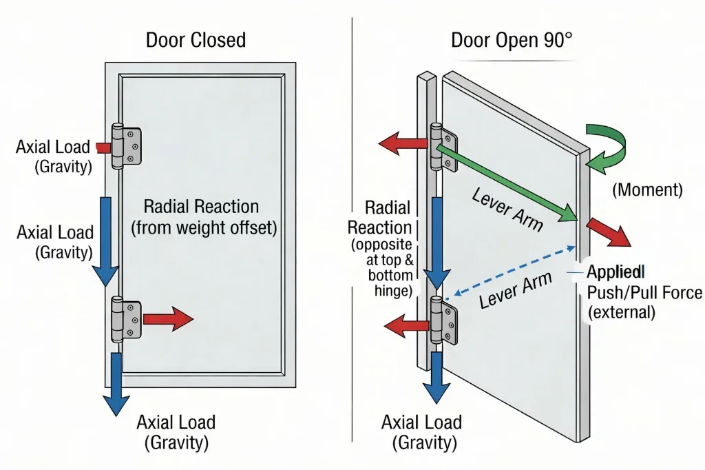
- Radial Load: This is the force perpendicular to the hinge pin axis. The weight of the door panel typically generates this force.
- Axial Load: Conversely, this refers to the force parallel to the hinge pin axis.
- Center of Gravity (CG): The physical center of the door panel’s mass. Significantly, if the CG deviates from the geometric center, it alters the forces on the hinge.
- Lever Arm: The perpendicular distance from the point of load application to the hinge fulcrum.
- Safety Factor: The ratio of the rated ultimate load to the actual working load. For industrial cabinet doors, designers usually set this at 2.0–4.0.
- Yield Strength: The maximum stress a material can withstand before permanent deformation occurs. Consequently, selection benchmarks should rely on yield strength, not tensile strength.
- Cycle Life: The number of opening/closing cycles a hinge can perform under rated load while maintaining functionality.
- Static Load Rating: The maximum load a hinge can withstand in a stationary state without failure.
- Dynamic Load: Instantaneous loads generated by door movement (acceleration/deceleration/impact).
- Salt Spray Test: A standardized test that evaluates the corrosion resistance of materials.
Application Scenarios & Constraints
However, before you calculate loads, you must define the physical boundary conditions.
Key Environmental & Physical Factors
- Environmental Exposure:
- Indoor: Focus on dust and light condensation (IP54).
- Outdoor: Furthermore, outdoor settings require focus on wind load, UV radiation, and salt spray (IP65/66, NEMA 4X).
- Food/Medical: These environments require resistance to chemical cleaning agents (Caustic Washdown).
- Installation Space:
- Door frame width limits hinge leaf size.
- Additionally, Concealed Hinges occupy effective internal depth within the cabinet.
- Load Path:
- Side-mounted doors primarily generate radial loads.
- In contrast, top-opening lids/covers primarily generate axial loads and bending moments.
- Operation Frequency:
- Maintenance Doors: < 10 times/month.
- Production Equipment Hatches: > 100 times/day. Therefore, focus on wear and fatigue.
Industry Benchmark Data
Use the following data for reference only. Ultimately, you must base actual values on the supplier’s Approval Sheet.
| Material | Common Process | Tensile Strength (Typical / Min) | Corrosion Req. & Acceptance (Finish + Test Method + Criteria) |
|---|---|---|---|
| SPCC / SPCCT (Carbon Steel) | Stamping | SPCCT: ≥ 270 MPa (Min) (Specify SPCCT for guaranteed tensile) | Finish: Zinc Plating (8-12 µm) Test: ASTM B117 (NSS) @ 96h Acceptance: Red rust < 1% area; Function OK |
| SUS 304 (Stainless Steel) | Stamping / Fabrication | Wrought (Annealed): Typical: 515–730 MPa Spec Min: ≥ 515 MPa | Finish: Passivated Test: ASTM B117 (NSS) @ 240h Acceptance: No Red Rust; Function OK |
| SUS 316 (Stainless Steel) | Investment Casting | Casting Grade: Specify Grade (e.g., CF8M) Spec Min: ≥ 485 MPa (typ.) | Finish: Passivated Test: ASTM B117 (NSS) @ 1000h Acceptance: No Red Rust; No Pitting; Function OK |
| Zinc Alloy (Zamak) | Die Casting | Zamak 3/5: Typical: 270–330 MPa Spec Min: ≥ 280 MPa | Finish: E-coat / Chrome (20-30 µm) Test: ASTM B117 (NSS) @ 480h Acceptance: White rust < 5%; No Base Metal Corrosion |
| Alu Alloy (Aluminum) | Extrusion / Die Casting | ADC12 (Die Cast): 180–240 MPa 6061-T6 (Extrusion): ≥ 290 MPa | Finish: Anodizing (Type II / III) Test: ASTM B117 (NSS) @ 480h Acceptance: Scribe creep < 2mm; Function OK |
Note: “Acceptance Criteria” for corrosion tests implies functional checks (opening/closing force change < 20%) in addition to visual inspection.
Note: Plating values vary by thickness. E.g., Blue Zinc is typically 72h to white rust, while Black Zinc is typically 96h.
Worked Examples
Heavy Duty Outdoor Cabinet
- Conditions: Door weight 80 kg, Height 2000 mm, Width 800 mm. The design uses 2 hinges. CG is at the geometric center.
- Formulas:
- Radial_Load_Per_Hinge = (DoorWeight / 2)
- Adjusted_Load = Radial_Load * SafetyFactor
- Calculation:
- Load per hinge = 80 kg / 2 = 40 kg (Approx. 392 N).
- Considering outdoor wind load and misuse, set SafetyFactor = 3.0.
- Selection Requirement: Consequently, the rated working load per hinge must be > 120 kg (1176 N).
- Note: If the door Width/Height ratio > 1, verify the Pull-out Force on the top hinge.
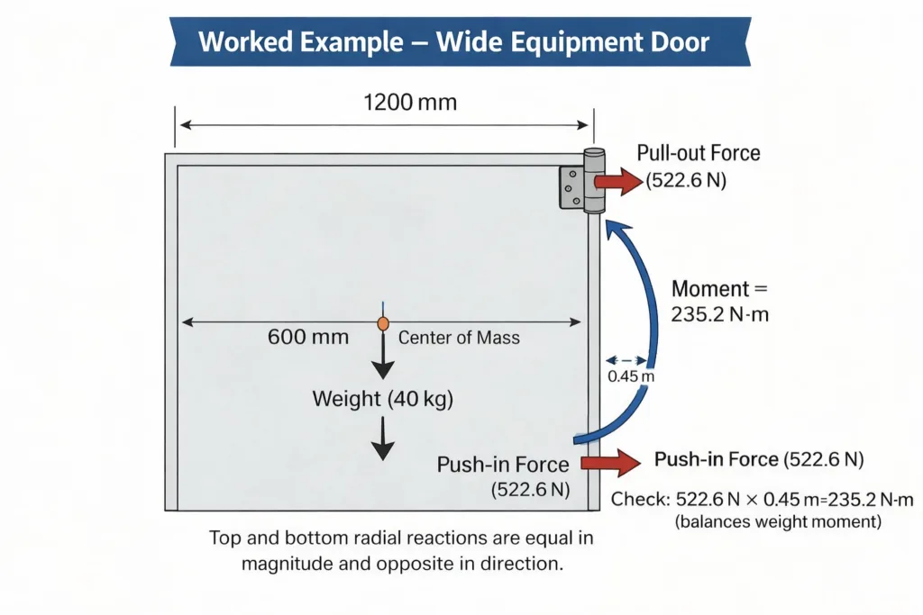
Wide Equipment Door (Non-Standard)
- Conditions: Door weight 40 kg, Width 1200 mm, Height 600 mm. Since width is greater than height, this creates significant moment effects.
- Formulas:
- Torque = DoorWeight * Gravity * Distance_to_CG
- Tensile_Load_Top_Hinge = Torque / Hinge_Spacing
- Calculation:
- Distance from CG to hinge axis = 600 mm (0.6 m).
- Hinge spacing = 450 mm (0.45 m).
- Torque = 40 kg * 9.8 m/s² * 0.6 m = 235.2 N·m.
- Horizontal tensile force on top hinge = 235.2 N·m / 0.45 m = 522.6 N.
- Conclusion: Although the vertical load is only 20 kg/hinge, the top hinge must withstand a horizontal pull-out force of 522.6 N. Standard lift-off hinges may fail. Therefore, a reinforced long-leaf hinge is required.
Good vs. Bad Methods
Comparing different approaches reveals crucial distinctions in quality and safety.
| Dimension | ❌ Bad Practice | ✅ Good Practice |
| Selection Basis | Selecting hinges based solely on “Door Weight,” ignoring width and thickness. | Calculating Moment, verifying combined radial and axial loads. |
| Safety Factor | Using the supplier’s “Ultimate Breaking Load” as the working load. | Setting Safety Factor ≥ 2.5, selecting based on yield strength. |
| Material Matching | Using carbon steel screws to fix hinges on stainless steel cabinets (causes galvanic corrosion). | Matching fastener material potential with hinge/cabinet, or using insulating washers. |
| Installation Position | Distributing hinges equidistantly (ignoring stress differences). | The top hinge carries the most load; appropriately shift the top hinge upward to reduce the moment. |
| Spec Sheet | Vague description: “High corrosion resistance required.” | Clear definition: “Complies with ASTM B117 Salt Spray Test 480 hours No Red Rust.” |
Industry Best Practices
Design Phase
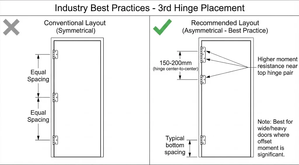
- 3-Hinge Configuration: For doors with height > 1500mm, we recommend using 3 hinges. Ideally, install the 3rd hinge 150-200mm below the top hinge, rather than in the middle of the door, to share the top tensile load.
- Simulation: Furthermore, for high-value equipment, perform FEA (Finite Element Analysis) to simulate stress concentration points.
Manufacturing & Assembly
- Welding vs. Fastening: Welded hinges require control of Heat Affected Zone (HAZ) rust risks. Conversely, screw fastening requires thread locker application (Loctite 243 or equivalent).
- Torque Control: Establish clear screw tightening torque standards (e.g., M6 Stainless Steel Screw: 9.0 N·m ± 10%).
Maintenance
- Develop a lubrication schedule. Additionally, specify the lubricant type (e.g., Lithium grease vs. PTFE dry lubricant).
Reliability Testing & Acceptance
You must include the following test clauses in the Purchase Order or Approval Sheet.
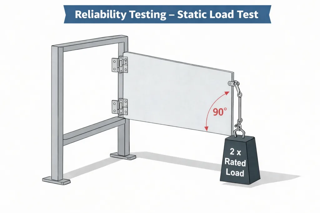
- Static Load Test:
- Reference Standard: ANSI/BHMA A156.1 (Butt Hinges) or EN 1935.
- Test Condition: Open the door panel to 90 degrees. Then, apply 2x Rated Load at the distal end of the door panel and maintain for 10 minutes.
- Acceptance Criteria: After unloading, the door panel sag must be < 1.0 mm (or 0.2% of door width). Also, ensure no visible deformation of the hinge and smooth operation.
- Cycle Life Test:
- Reference Standard: EN 1935 Grade 11 or internal corporate standard.
- Test Condition: Hang rated weight. Subsequently, run at a frequency of 6-10 times/minute with an opening angle of 0°-90°-0° for 25,000 cycles.
- Acceptance Criteria: Wear after test < 0.5 mm, torque change rate < 20%, and no breakage.
- Salt Spray Test:
- Reference Standard: ASTM B117 or ISO 9227 (NSS).
- Test Condition: Use 5% NaCl solution at 35°C. Spray continuously for the specified duration (e.g., 96h for Indoor/IP54, 720h+ for Outdoor/Marine).
- Acceptance Criteria: No Red Rust on the surface and blistering area < 1%. (For SUS316, require 1000+ hours with no rust spots).
Failure Mode and Effects Analysis
The table below simplifies potential failure modes and their mitigation strategies.
| Failure Mode | Cause | Effect | Detection | Mitigation |
| Pin Shear | Load exceeds design value, impact load | Door panel detachment, safety accident | Destructive testing | Increase pin diameter, switch to high-strength steel |
| Leaf Bent | Plate material too thin, lever arm too large | Door panel sag, seal failure | Gap measurement | Increase plate thickness, add reinforcing ribs |
| Seizure (Corrosion) | Incorrect material selection, dissimilar metal contact | Door cannot open, destructive removal required | Salt spray test | Upgrade material (304->316), add insulating pads |
| Loosening | Vibration, no thread locker applied | Hinge displacement | Torque check | Pre-applied adhesive screws, lock washers |
| Bushing Wear | No lubrication, high-frequency use | Noise generation, door panel wobble | Cycle life test | Use oil-impregnated bearings or self-lubricating materials |
| Damping Loss | Damping grease leakage, hardening at low temp | Violent door impact | Low-temperature test | Select wide-temperature range damping grease (-40°C~80°C) |
Operational Checklist
Pre-Selection
- Confirm Door Panel Weight (kg) and Dimensions (H x W x D).
- Confirm Max Opening Angle (110° / 180° / 270°).
- Confirm Installation Environment (Indoor/Outdoor/Seaside/Chemical Plant).
- Calculate torque at the point of maximum stress.
Prototyping
- Perform physical trial assembly and check for interference.
- Perform 24-hour Salt Spray screening (for surface-treated parts).
- Tactile confirmation (torque consistency).
Incoming QC
- Dimensional check (Critical mounting hole spacing tolerance ±0.5 mm).
- Visual check (No burrs, no coating peeling).
- Material Spectrum Analysis (PMI) sampling (Confirm 304/316 Nickel/Chromium content).
FAQ
Q1: Why does the door panel still sag even if the total load capacity meets the requirements?
A: Usually, this happens because the designer ignored “Torque” and “Rigidity.” If the door is very wide (long lever arm), the tensile force on the top hinge will exceed the door’s weight. Additionally, if the cabinet column steel plate is too thin, the cabinet itself may deform even if the hinge does not, leading to sag. Therefore, you need a Backing Plate for reinforcement.
Q2: A 304 stainless steel hinge showed rust spots when used at the seaside. Is the material fake?
A: Not necessarily. 304 stainless steel can still suffer from pitting corrosion in high chloride environments (sea mist). Consequently, for seaside or marine applications, we strongly recommend using 316 Stainless Steel treated with Electropolishing to maximize corrosion resistance.
Q3: How do I convert NEMA ratings to IP ratings?
A: This is an approximate conversion, not an exact equivalent.
- NEMA 4 ~ IP66 (Dust + Strong Water Jet).
- NEMA 12 ~ IP54 (Dust + Dripping/Splashing Water).
- NEMA 4X adds extra corrosion resistance requirements. Since there is no direct correspondence in the IEC 60529 IP standard, you must superimpose ASTM B117 requirements.
Q4: What should the Safety Factor be for industrial hinges?
A: For static load applications, we recommend 2.0 – 2.5. However, for dynamic loads (vehicles, frequently vibrating equipment), use 3.0 – 4.0. Never use the “Ultimate Breaking Load” directly as the design basis.
Q5: Which has stronger load capacity: welded hinges or screw-fixed hinges?
A: Welding typically provides stronger connection strength but is limited by welding process stability (porosity, incomplete fusion). In contrast, screw fixation (with backing plates) is more standardized and easier to replace. For extremely high loads, recommend Through-bolt installation over simple self-tapping screws.
Q6: Is UL certification mandatory for hinges?
A: For Fire Doors, compliance with UL 10C or NFPA 80 standards is mandatory. While not mandatory for general industrial cabinet doors, compliance with RoHS/REACH and specific mechanical performance standards (such as BHMA) is typically required.

Anson Li
文章: 595RELATED POSTS
Industrial Hinges in Extreme Temperatures (-40°C to +200°C): A Manufacturer’s Engineering Guide
Difference between removable and fixed hinges
Rotational Torque Hinges Explained: How They Improve Stability, Usability, and Design
-1-768x768.png)
Hardware Handles A Comprehensive Guide for Wholesalers
Enclosure Cabinet Handles Essential Choices for Your Space