HTAN is one of the leading manufacturers of industrial hinges, handles and latches in China.


Continuous hinges, commonly referred to as piano hinges, provide a reliable method for distributing load along the entire length of a metal enclosure door. When correctly cut, positioned, and fastened, they improve door alignment stability, reduce localized stress at mounting points, and support repeatable sealing performance.
This guide details the technical procedures for cutting and installing these components to support structural integrity, alignment control, and alignment with common industrial validation expectations.
Core Definitions and Industry Benchmarks
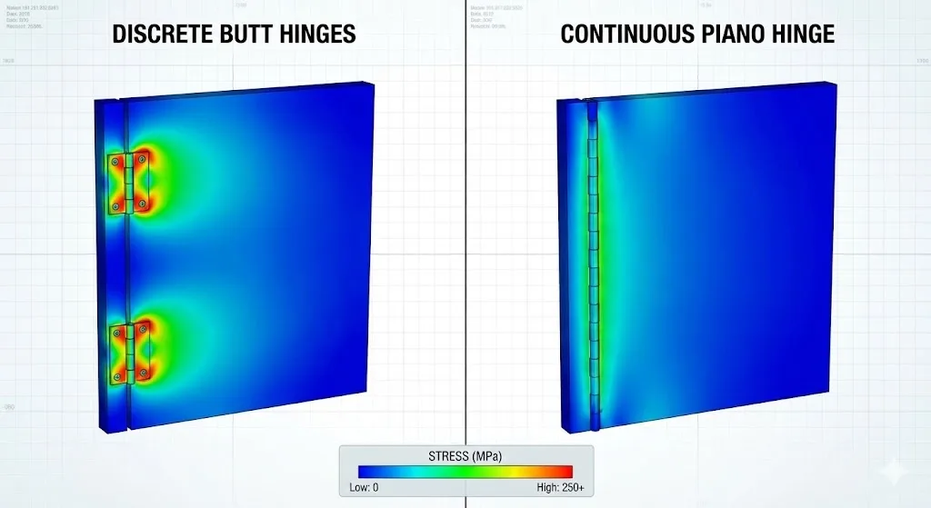
A Continuous Hinge is a high-aspect-ratio hinge consisting of two leaves joined by a central pin. Unlike discrete butt hinges, it reduces the risk of door sag by distributing support along the entire hinge length.
Key Performance Indicators (KPIs)
The following KPIs serve as engineering indicators for design reviews and production acceptance:
- Load Distribution (Indicator): A practical comparison metric is the door weight per hinge length (kg/m) and fastener spacing (mm).
- Pin Retention: The ability of the central pin to remain stationary under vibration and cyclic opening. This is influenced by pin end treatment (staking/crimping).
- Lateral Play: The maximum allowable horizontal movement between leaves. For industrial enclosures requiring consistent reveal, lateral play is typically restricted to < 0.5mm.
Industry Standards
- ASTM A240: Standard specification for chromium and chromium-nickel stainless steel.
- ISO 9227: Corrosion tests in artificial atmospheres (Salt spray tests).
- EN 1935: Single-axis hinges requirements and test methods. Manufacturers often supplement this with internal cycle tests and vibration testing.
Material Selection and Technical Specifications
Material selection must consider corrosion resistance, strength-to-weight ratio, and galvanic compatibility with the enclosure substrate.
| Material | Standard Grade | Corrosion Resistance | Strength-to-Weight Ratio | Best Use Case |
| 304 Stainless Steel | ASTM A240 | High | Moderate | Indoor/General Industrial |
| 316 Stainless Steel | ASTM A240 | Superior | Moderate | Marine/Chemical Processing |
| Aluminum | 6063-T5 | Moderate | High | Lightweight Electronics |
| Galvanized Steel | EN 10346 | Low/Moderate | Low | Cost-sensitive utility boxes |
Mathematical Preparation and Thermal Margins
Before cutting, precise calculations are required to account for clearance (gap), coating thickness, and thermal expansion.
Base Clearance Formula
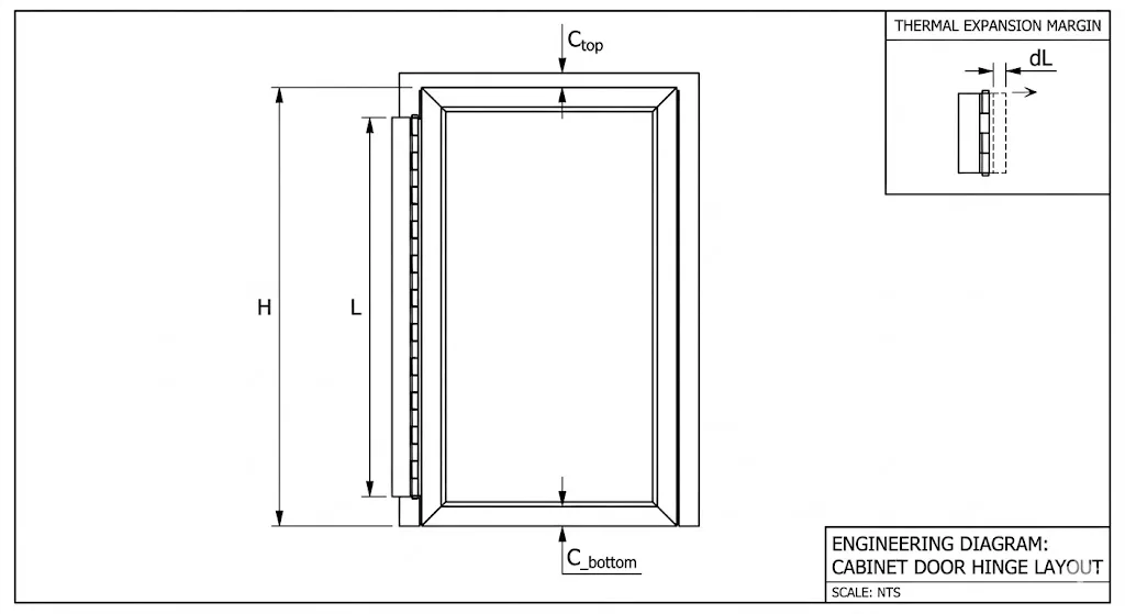
L = H – (C_top + C_bottom)
- L: Final hinge length.
- H: Total height of the enclosure door opening.
- C_top/C_bottom: Required top/bottom clearance (typically 1.0mm – 2.0mm).
Thermal Expansion Consideration
Thermal Expansion Consideration If the enclosure operates in extreme temperature swings, include a thermal margin (M) to account for the linear expansion coefficients of the materials used.
Thermal expansion (dL) = H x alpha x dT
- alpha (steel): approx. 12e-6 / degree C
- alpha (aluminum): approx. 23e-6 / degree C
- dT: Operating temperature swing (degree C)
- Adjusted Length: L_final = H – (C_top + C_bottom) – (0.5 x dL)
Execution Step-by-Step
Step 1: Precision Cutting and Contamination Control
- Process: Use a Cold Saw or an Angle Grinder with a 1mm ultra-thin inox disc.
- Stabilization: Close the hinge completely before cutting to stabilize the pin.
- Heat Management: Avoid excessive heat, which causes “blueing” (heat tint). Heat tint reduces corrosion resistance at the cut edge.
- Contamination: If working near electrical components, isolate the area. Metal chips can create short circuits.
Step 2: Deburring and Edge Treatment
- Mechanical Processing: Use a fine-tooth file or deburring tool to achieve a slight radius (approx. 0.5mm).
- Passivation: For stainless steel, apply a passivation solution to restore the chromium oxide protective layer after removing heat tint.
- Pin Retention: Perform staking or crimping at the hinge ends to prevent pin migration.
Step 3: Drilling and Fastener Spacing
- Accuracy: Use a Center Punch to mark each hole center. Failure to do so increases drill bit wander.
- Drilling: Use low RPM and cutting fluid for stainless steel to prevent work hardening.
- Spacing Baseline:
- General Industrial: 75mm to 100mm spacing.
- Heavy-Duty/High-Cycle: 50mm to 75mm spacing.
Step 4: Mounting and Torque Lock-down
- Sequence: Fix top and bottom fasteners first to establish reference alignment, then work from the center outwards.
- Hardware: Use M5 or M6 machine screws or structural rivets (ISO 15977).
- Anti-Vibration: Apply a thread-locking compound to reduce torque decay over duty cycles.
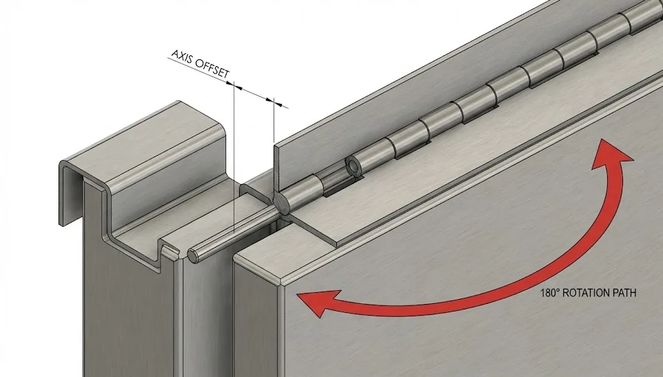
- Axis Offset: Ensure the hinge axis is sufficiently offset from return flanges to prevent “spring-back” during closure.
Comparative Analysis: Best Practices vs. Substandard Methods
| Feature | Industry Best Practice | Substandard Method | Impact of Failure |
| Cutting | Cold saw with coolant | Abrasive saw (high heat) | Heat tint, localized rust |
| Hole Marking | Center punch & template | Free-hand drilling | Door misalignment, binding |
| Deburring | Mechanical deburring + Passivation | Left as-cut | Injury risk, seal damage |
| Fastening | Structural Rivets/Machine Screws | Wood screws / Tack welding | Fastener shear, poor maintenance |
Failure Mode and Effects Analysis (FMEA)
| Potential Failure Mode | Potential Cause | Potential Effect | Mitigation Strategy |
| Pin Migration | Lack of staking/crimping | Hinge failure; door separation | Stake/crimp knuckles after cutting. |
| Hinge Binding | Misalignment; insufficient offset | Excessive force; spring-back | Template drilling; check axis clearance. |
| Galvanic Corrosion | Dissimilar metals | Joint degradation; seizure | Use dielectric barriers/nylon washers. |
| Torque Decay | Vibration; material creep | Loose fasteners; alignment drift | Lock nuts; thread-lock compound. |
Reliability Testing and Acceptance Criteria
- Swing Test: Door rotates through full range (180/270 degrees) without audible friction or leaf interference.
- Alignment Check: The reveal (door-to-frame gap) must be consistent within +/- 0.5mm.
- Load Test: Apply max rated load; outer edge deflection should not exceed 1% of door width.
- ISO 9227: Verify corrosion resistance of cut edges via salt spray exposure for the required duration.
Final Installation Checklist
- [ ] Material grade verified (304/316/Al/Galvanized).
- [ ] Hinge cut to length within +/- 0.5mm tolerance.
- [ ] Cut edges deburred, heat tint removed, and passivated.
- [ ] Pin ends crimped/staked to prevent migration.
- [ ] Fastener spacing matches duty class (50-100mm).
- [ ] Axis offset verified to prevent flange interference.
- [ ] All metal chips/debris removed from enclosure interior.
FAQ: Technical Troubleshooting
Q1: Can I cut a continuous hinge after it is already installed?
A: Not recommended. This introduces metal shavings into electrical components and risks damaging the enclosure’s coating. Always process the hinge before mounting.
Q2: How do I prevent rust on the cut edges of a stainless steel hinge?
A: Mechanically polish the edge to remove heat tint and apply a passivation chemical. This restores the protective chromium oxide layer.
Q3: What should I do if the hinge pin starts to slide out after cutting?
A: Stake or crimp the end of the last knuckle using a hammer and center punch to create a mechanical lock.
Q4: Is it better to weld or screw a continuous hinge onto a metal box?
A: Mechanical fasteners are preferred for alignment control and serviceability. Welding increases the risk of heat distortion and complicates repair.
Q5: What is the maximum weight a 2-inch wide piano hinge can hold?
A: There is no universal value. Capacity depends on pin diameter, leaf thickness, fastener spacing, and substrate stiffness. Always verify with a deflection test on the actual structure.
Q6: Why is my door “springing” back slightly when I try to close it?
A: This is usually “hinge bind” caused by insufficient axis offset from the return flange or fasteners that are not seated flush.

Anson Li
文章: 576RELATED POSTS
Rotational Torque Hinges Explained: How They Improve Stability, Usability, and Design
Outdoor Cabinet Cam Locks: Applications and Advantages
Best Equipment Door Hinge Solutions
Industrial Cabinet Door Not Closing? Concealed Hinge Fix Guide
Torque Hinges for Table Lamps – Smooth Angle Adjustment & Sturdy Support