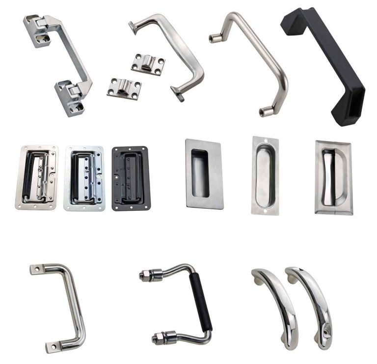
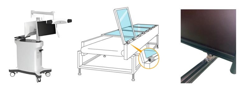
HTAN est l'un des principaux fabricants de charnières, de poignées et de loquets industriels en Chine.


A machine door hinge assembly validation should prove more than whether a loose hinge looks correct or rotates on an inspection bench. The completed door may still sag after its temporary support is removed, bind after a welded frame is released from its fixture, or shift after a bolt-on joint is finally tightened and loaded.
The representative assembly must include the production-intent door, frame, hinge mounting structure, door-mounted hardware, latch or interlock, opening restraint, finish condition, and any cable, hose, or bonding connection that moves with the door. Validation then compares measurable geometry and function before and after the operating conditions that could change alignment.
This guide explains how to prepare that assembly, establish a valid baseline, run a project-specific operating exposure, repeat the measurements, and decide whether the result supports production release or requires corrective action and resampling.
Validation Boundary
This article validates an installed machine-door assembly. It does not replace incoming inspection of the loose hinge component, supplier process validation, first-article inspection, or ongoing production inspection.
If the attachment method has not been selected, begin with the Guide d'aide à la décision : charnières à souder ou à visser. Assembly validation should begin only after the hinge architecture and mounting method are defined.
Define and Identify the Representative Machine-Door Assembly
A hinge mounted to a small test plate may demonstrate basic rotation, but it does not reproduce the complete door moment, frame flexibility, latch position, mounting compliance, cable resistance, finish buildup, or opening restraint of the production machine.
Before testing, identify exactly what the assembly represents and connect every relevant component to its drawing or specification revision.
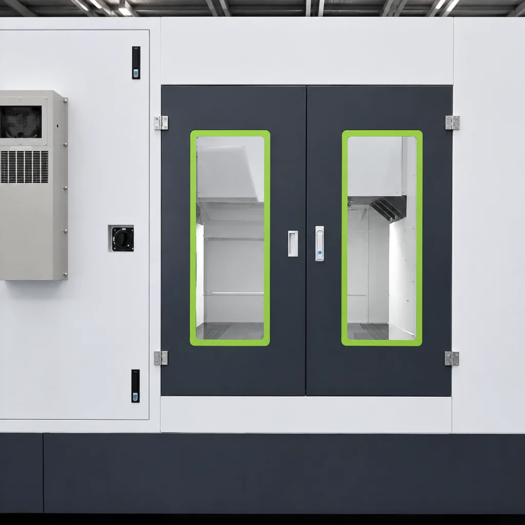
| Assembly element | Production-intent representation | Risk if omitted or substituted incorrectly |
|---|---|---|
| Structure de la porte | Panel, inner frame, returns, reinforcement, windows, mesh, insulation, guards, and removable covers | The sample may not reproduce final stiffness, mass distribution, or center of gravity |
| Door-mounted hardware | Handles, latches, linkage, HMI parts, fans, indicators, interlock actuators, and cable hardware | The tested door may be lighter or differently balanced than production |
| Machine frame | Representative tube, plate, formed flange, extrusion, mounting pad, or structural opening | Frame deflection and hinge support are not represented |
| Fixation par charnière | Production-intent weld condition or fastener, backing plate, insert, shim, spacer, and hole pattern | The test validates the hinge but not the installed joint |
| Closing interface | Latch, strike, gasket, door stop, guard overlap, or interlock actuator | Closed-position repeatability cannot be evaluated |
| Opening control | Stop, stay, detent, torque hinge, chain, cable restraint, or separate support | The hinge may receive unintended overtravel or impact loads |
| Moving services | Electrical cable, hose, grounding strap, bonding conductor, connector, and service loop | Routing resistance or interference may change door motion and alignment |
| Surface condition | Production-intent coating, plating, masking, paint buildup, and bare joint areas | Clearances, friction, and bolted contact conditions may change later |
The assembly record should identify the hinge model or part number, handing, hinge count, door drawing, frame drawing, latch revision, mounting specification, finish state, and test-fixture condition.
Where a final component is unavailable, document the substitute and explain how it represents the missing component’s mass, center of gravity, stiffness, rotational inertia, mounting compliance, cable stiffness, stop behavior, and interference envelope. Mark unverified conditions Préliminaire ou À confirmer.
Bring the Assembly to Its Production-Intent Condition
Formal baseline measurements should not be taken while the door is partially assembled, temporarily supported, restrained by a welding fixture, or missing its final hardware. The assembly must first reach the condition that production is expected to reproduce.
- Complete the hinge mounting process. Finish the specified weld condition or complete the released bolt-on assembly and tightening procedure.
- Allow welded structures to reach the defined inspection state. Complete cooling and release the applicable welding or alignment fixture before establishing the final baseline.
- Complete production-intent finishing. Apply the intended paint, coating, plating, masking, or surface treatment where it affects clearance or joint seating.
- Install the complete moving hardware. Add windows, handles, latch parts, HMI components, cables, hoses, grounding straps, insulation, guards, and covers.
- Install the production closing and opening interfaces. Include the latch, strike, gasket, stop, stay, detent, restraint, and mechanical interlock hardware where applicable.
- Remove temporary door support. The hinge and frame must carry the representative door without a fixture hiding sag or joint movement.
- Set the representative frame condition. Support, level, or mount the frame as defined by the validation plan.
Baseline rule: Do not treat measurements taken before final loading, final tightening, fixture release, finish application, or temporary-support removal as the formal production-intent baseline.
Apply the Complete Moving-Door Load and Establish the Baseline
The relevant test load is the complete assembly that rotates with the hinge, not only the bare panel. Record the complete moving mass and the center-of-gravity location relative to the hinge axis. Use the separate Guide sur la capacité de charge des charnières de portes industrielles to establish the underlying load inputs and preliminary hinge sizing.
Do not attach an arbitrary test weight without documenting its position. Equal masses placed at different distances from the hinge axis create different door moments. For powered, fast-moving, or impact-limited doors, also review mass distribution, rotational inertia, opening speed, actuator force, stop deceleration, and possible slam conditions.
After the complete load is installed and temporary support is removed, establish repeatable geometry and functional measurements.
| Baseline item | Measurement method or reference | Pourquoi est-ce important ? |
|---|---|---|
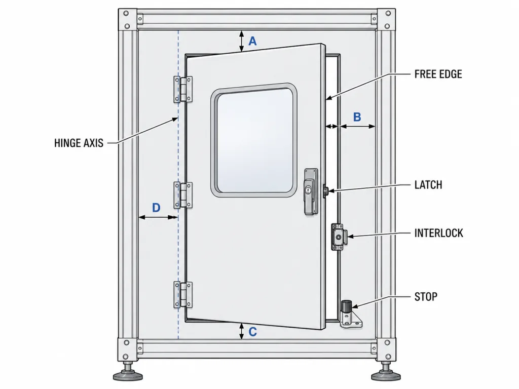
| Hinge-axis reference | Alignment mandrel, removable reference pin, barrel centerline feature, specified leaf datum, or validated rotational path | Provides a repeatable reference for detecting axis movement or non-coaxial hinges |
| Free-edge height | Defined point near the latch side with the door in a specified position | Reveals sag, frame deflection, or mounting movement |
| Perimeter gap | Defined points A, B, C, and D around the closed door | Shows door twist, angular movement, and uneven closing |
| In-out position | Door plane relative to the machine opening before latch engagement | Identifies leaf movement, gasket resistance, or latch overpull |
| Latch position | Strike entry path, engagement position, and closing movement | Shows whether the latch is compensating for hinge or frame error |
| Interlock alignment | Actuator entry path and mechanical clearance | Identifies side loading or positional drift at the mechanical interface |
| Angle d'ouverture | Door position against the specified stop, stay, detent, or restraint | Confirms the intended access envelope and overtravel control |
| Door operating force | Defined handle point, direction, door angle, speed, and temperature | Detects binding, seal drag, cable resistance, or changing friction |
| Hinge torque | Record only where a torque or friction hinge is specified | Confirms the specified position-control function without confusing it with general door force |
ASME Y14.5 can provide a standardized language for datums, dimensions, and geometric tolerances on the released drawing. It does not define the project’s acceptable door gap, cycle count, load, sample quantity, measurement instrument, or pass/fail limit.
Measurement consistency: Use the same door position, frame support, datums, measurement points, instruments, and operating method before and after testing. A change in measurement setup can look like a change in the assembly.
Verify Full Motion and the Closing Interfaces
A door should not be approved from only the fully open and fully closed positions. Binding, cable tension, barrel interference, frame contact, and door rise or fall may occur at only one part of the swing.
| Door position | Vérifier | Possible concern |
|---|---|---|
| Initial opening | Latch release, gasket separation, cable movement, and breakaway force | Latch interference, seal adhesion, cable tension, or excessive friction |
| Mid-swing | Change in operating force, pin movement, frame clearance, and vertical door movement | Non-coaxial hinges, frame twist, bent pin, or incorrect shimming |
| Maximum opening | Stop or stay engagement, service access, cable reserve, and adjacent-equipment clearance | Overtravel, cable strain, impact into the hinge, or blocked maintenance space |
| Closing approach | Door position before the latch, gasket, or interlock begins to engage | Misalignment hidden by the closing hardware |
| Fully closed | Gap repeatability, latch engagement, gasket condition, and reopening force | Latch overpull, excessive seal compression, sticking, or free-edge drift |
A free-swing hinge is not required to hold the door at an arbitrary angle. Confirm instead that the specified stop, stay, detent, torque hinge, or separate restraint controls the required open position.
Where a cable, hose, bonding strap, grounding conductor, or connector crosses the hinge side, confirm that it follows a controlled service loop through the complete movement. The moving service must not pull the door away from its measured path or become pinched by the leaf, frame, stop, or latch.
The latch should engage without lifting, twisting, or pushing the free edge sideways. Record the door position immediately before latch engagement so that latch force does not conceal hinge or frame error.
An interlock check in this article validates only the mechanical actuator position, clearance, and absence of side loading. It does not validate the safety circuit, guard-locking function, diagnostic coverage, or required functional-safety performance.
Use the Correct Validation Checkpoint for the Mounting Method
The door-level acceptance measurements are similar for welded and bolt-on assemblies, but the correct inspection checkpoint is different.
| Mounting method | Production-intent checkpoint | Assembly-level evidence |
|---|---|---|
| Welded hinge | After final welding, cooling, fixture release, and relevant surrounding frame welding | Hinge-axis reference, door gaps, free-edge position, full motion, latch alignment, and visible weld or frame condition |
| Charnière à boulonner | After final tightening, shim placement, temporary-support removal, and representative loading | Leaf position, door gaps, free-edge position, full motion, latch alignment, and visible evidence of joint movement |
For welded mounting design, fixture control, and post-weld alignment details, use the welded machine frame door hinge guide.
For bolt patterns, backing support, threads, shims, adjustment, and joint architecture, use the bolt-on machine frame door hinge guide.
Fastener witness marks may provide supplemental evidence of visible relative movement, but they do not verify bolt preload or complete joint integrity. The released tightening process, calibrated tools, joint seating, leaf movement, fretting, washer embedding, and local deformation should be reviewed together.
Run the Project-Specific Operating Exposure
No universal cycle count applies to every machine door. The validation condition should reflect how the equipment is expected to be operated, maintained, transported, and installed.
| Test field | What the validation plan should state |
|---|---|
| Cycle count or duration | Project-Specific requirement based on access frequency and equipment duty |
| Charge sur la porte | Complete moving mass, center-of-gravity condition, and applicable mass distribution |
| Motion range | Opening angle, closing position, stop condition, and any intermediate operating positions |
| Operating method | Manual or powered motion, handle point, actuator condition, speed, and permitted slam or impact condition |
| Environnement | Temperature, contamination, humidity, washdown, dust, or other Project-Specific exposure |
| Lubrification | Initial state, allowed maintenance, lubricant specification, and any relubrication interval |
| Inspection points | Intermediate cycle counts or events requiring measurements and visual review |
| Critères d'acceptation | Allowable geometry change, operating-force change, visible damage, latch function, and interlock alignment |
| Measurement uncertainty | Instrument capability and method appropriate to the specified acceptance limit |
Supplier hinge test data may support engineering review, but it should identify the tested model, fixture, load, orientation, temperature, cycle count, speed, lubrication, acceptance criteria, result, and report number or date. Data generated with a different mounting orientation, load path, or door moment may not represent the machine-door assembly.
Repeat the Baseline Measurements After Testing
Do not close the test report with the statement that the door “still works.” Repeat the original measurements using the same frame condition, datums, door positions, tools, and operating method.
| Post-test evidence | Compare with baseline | Possible disposition |
|---|---|---|
| Hinge-axis reference | Position or coaxiality change | Pass or review mounting movement, frame distortion, or hinge wear |
| Free-edge position | Vertical and in-out change | Pass or review sag, frame deflection, and joint movement |
| Perimeter gaps | Change at defined points A–D | Pass or review door twist, angular shift, or latch overpull |
| Door operating force | Change through the same motion range | Pass or review binding, contamination, cable drag, seal condition, and friction |
| Latch and mechanical interlock | Entry path, side loading, and closing repeatability | Pass or review hinge position, stop location, door sag, or closing interface |
| Mounting interface | Visible movement, fretting, local deformation, weld condition, or insert movement | Pass, corrective action, or resampling |
| Opening control | Stop, stay, detent, torque hinge, or restraint position | Pass or review overtravel and dynamic loading |
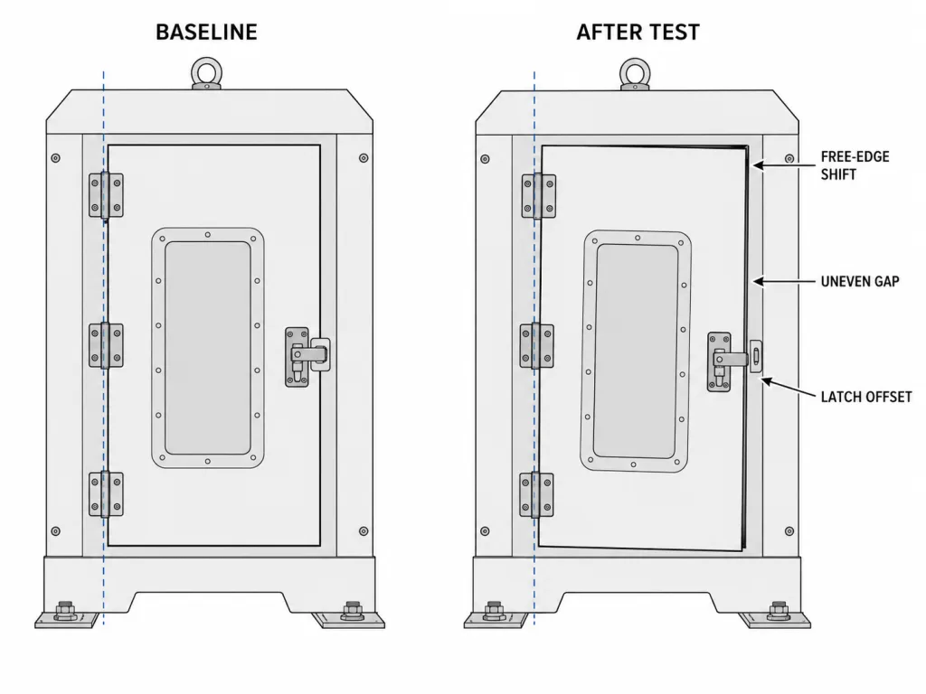
Any measured change should be compared with a Project-Specific functional limit. A cosmetic gap change may be acceptable on one machine but unacceptable where it affects a latch, seal, interlock, guard overlap, pinch clearance, or adjacent component.
Recheck Conditional Installation and Service Exposures
Some machine doors change position only after installation, transport, maintenance, or environmental exposure. Include these checks only where they match the real production or service sequence.
| Conditional exposure | Why it may change the assembly | Repeat after exposure |
|---|---|---|
| Machine leveling or anchoring | The base or frame may twist as supports and anchors are adjusted | Door opening, gaps, free-edge position, latch, and interlock path |
| Transport or vibration | Joint seating, frame movement, and door-mounted mass may change alignment | Mounting interface, gaps, latch, cables, and opening control |
| Door removal and reinstallation | Shims, clearance holes, removable pins, or locating features may not return to the original position | Axis reference, gaps, free-edge height, and closing repeatability |
| Field hinge replacement | Replacement geometry or mounting position may differ from the approved assembly | Full baseline set and complete motion |
| Temperature or environmental exposure | Materials, seals, lubricants, coatings, and clearances may respond differently | Operating force, gaps, latch, stop, and visible mounting condition |
| Maintenance intervention | Fastener removal, lubrication, cable service, or component replacement may alter the system | Relevant baseline measurements and motion path |
Decide Whether the Assembly Passes, Requires Correction, or Needs Resampling
A failed measurement does not automatically mean the hinge needs a higher load rating. The result may be caused by the door, frame, mounting interface, closing hardware, moving services, opening restraint, or test configuration.
Corrective action should identify the affected drawing or process and determine whether the approved test configuration has changed.
| Change after initial validation | Typical disposition |
|---|---|
| Hinge model, leaf geometry, pin, bushing, offset, or handing changes | Engineering review and representative resampling normally required |
| Hinge count, spacing, or axis location changes | Repeat complete load, geometry, motion, and closing-interface validation |
| Bolt pattern, slot, backing plate, insert, shim, or tightening process changes | Repeat bolt-on assembly validation |
| Weld location, weld condition, fixture, sequence, or frame reinforcement changes | Repeat post-weld and fixture-release validation |
| Door mass, center of gravity, mass distribution, or major door-mounted hardware changes | Review load inputs and repeat representative testing |
| Latch, strike, gasket, stop, stay, or mechanical interlock position changes | Repeat full motion and closing-interface checks |
| Cable, hose, bonding strap, or service-loop routing changes | Repeat the complete motion and interference review |
| Finish or coating changes that affect seating, friction, or clearance | Repeat the affected baseline and motion checks |
| Only a documented nonfunctional cosmetic feature changes | Engineering may determine that full resampling is unnecessary |
A deviation may be accepted only against a documented Project-Specific requirement and authorized disposition. Do not convert an out-of-limit result into an informal new tolerance because the door can still be forced closed.
Composite Engineering Scenario: A Machine Guard Service Door
Il s'agit d'un scénario technique fictif élaboré afin d'expliquer la logique de sélection. Il ne s'agit ni d'un dossier de projet client ni d'un rapport d'essai de produit.
Consider a tall service door for an automated machine guard. The door includes a steel inner frame, transparent panel, handle, latch linkage, mechanical interlock actuator, and a cable leading to a door-mounted control component. Three bolt-on hinges attach the door to a formed machine-frame opening.
The first inspection is performed while the door is still supported on an assembly stand and before the final cable and viewing panel are installed. The door appears square, and the latch closes. Those measurements are recorded as the baseline.
This is not a valid production-intent baseline. The assembly is incomplete, and the temporary stand prevents the hinges and frame from carrying the full door moment.
The validation team installs the final panel and cable, completes the fastener tightening process, removes the temporary support, and positions the frame in its representative mounting condition. The free-edge height, perimeter gaps, door plane, latch path, operating force, and interlock clearance are then recorded.
After the project-specific cycle exposure, the upper gap and latch-side position change. The fastener witness marks do not show obvious rotation, but light fretting appears at the upper hinge leaf. Because witness marks do not prove preload, the review includes joint seating, backing support, tightening records, leaf movement, frame compliance, and cable resistance.
The corrective action changes the upper backing support and cable service loop. Because these changes affect the mounting interface and door motion, the revised complete assembly is resampled rather than approving only the replacement hinge.
Record Evidence That Production Can Reproduce
A signed photograph and the statement “assembly approved” do not establish what was tested. The record should allow engineering, quality, production, and the hinge supplier to reconstruct the validation condition.
| Evidence item | Required content |
|---|---|
| Assembly identity | Hinge, door, frame, latch, stop, finish, mounting, cable, and revision information |
| Production-intent status | Completed weld or tightening state, fixture release, finish condition, installed hardware, and support condition |
| Load configuration | Complete moving mass, center of gravity, orientation, and relevant mass distribution |
| Baseline record | Axis reference, free-edge position, perimeter gaps, door plane, latch, interlock, opening angle, and operating force |
| Operating exposure | Cycle count, speed, opening range, environment, lubrication, stops, and permitted maintenance |
| Post-test measurements | Repeated baseline values and visible mounting-interface inspection |
| Conditional exposures | Leveling, anchoring, transport, removal, reinstallation, replacement, or environmental conditions reproduced |
| Photographs | Complete assembly, mounting interfaces, closing hardware, measurement setup, and observed changes |
| Deviation record | Requirement, result, root-cause status, corrective action, disposition, and resampling decision |
| Traceability | Report number or date, instruments, calibration status, inspector, and approval authority |
Machine Door Hinge Assembly Validation Checklist
- The hinge, door, frame, mounting method, closing hardware, and revisions are traceable.
- The assembly includes the complete production-intent moving mass and center-of-gravity condition.
- Final welding or bolt tightening is complete before the formal baseline is recorded.
- Welded structures are cooled and released from the applicable fixture.
- The production-intent finish and door-mounted components are installed.
- Temporary door support is removed before baseline measurements.
- The hinge axis is related to a repeatable datum or measurement method.
- Free-edge position, perimeter gaps, door plane, latch path, and operating force are recorded.
- The door moves through the complete intended range without binding or uncontrolled overtravel.
- The specified stop, stay, detent, torque hinge, or restraint controls the required open position.
- Cables, hoses, and bonding connections move without pulling or pinching.
- The latch does not lift, twist, or force the door into alignment.
- The mechanical interlock interface is aligned without being treated as proof of functional-safety validation.
- The project-specific operating exposure and acceptance criteria are documented.
- The same baseline measurements are repeated after testing.
- Relevant installation, transport, removal, or environmental exposures are repeated where required.
- Witness marks are used only as supplemental evidence, not as proof of fastener preload.
- Design or process changes that affect the approved configuration trigger engineering review and resampling where required.
A preliminary recommendation identifies a possible hinge architecture. Engineering review confirms the proposed interface. Component sample approval confirms the loose hinge evidence. Assembly validation confirms the representative installed door. Production release additionally requires controlled drawings, BOMs, manufacturing processes, inspection methods, and change control.
Questions fréquemment posées
When should machine-door baseline measurements be taken?
Take the formal baseline after the hinge mounting process is complete, welded structures have cooled and been released from the applicable fixture, bolt-on joints have received final tightening, the production-intent finish and door hardware are installed, the complete moving load is present, and temporary door support has been removed.
How many cycles should a machine door hinge assembly complete?
There is no universal cycle count for every machine door. The requirement should reflect the equipment duty, expected access frequency, complete door load, opening range, motion speed, environment, maintenance plan, and project-specific acceptance criteria.
Does a free-swing machine door need to remain open without support?
Not unless the design specifies that function. A free-swing hinge only needs to move through the required range without binding. The required open position should be controlled by the specified stop, stay, detent, torque hinge, or separate restraint.
Do fastener witness marks prove that a bolt-on hinge joint is tight?
No. Witness marks may show visible relative movement, but they do not verify bolt preload or complete joint integrity. Review the released tightening process, calibrated tools, joint seating, leaf movement, fretting, washer embedding, and local deformation.
Does correct interlock alignment validate the machine safety system?
No. This assembly validation checks only the mechanical actuator position, entry path, clearance, and absence of side loading. It does not validate the safety circuit, guard-locking function, diagnostics, or required functional-safety performance.
When does a machine door assembly need to be resampled?
Resampling is normally required when a change affects the hinge model, hinge count or position, mounting structure, weld condition, bolt pattern, frame reinforcement, complete door load, center of gravity, latch, stop, interlock, moving-service routing, finish clearance, or another validated functional interface.
Release the Assembly From Measured Evidence
A successful machine door hinge assembly validation does not prove only that the hinge opens and closes. It confirms that a defined hinge, mounting interface, loaded door, machine frame, latch, stop, interlock, finish condition, and moving-service path work together under a documented test condition.
If the assembly passes only while supported, clamped, unfinished, partially loaded, or forced into position by its latch, it has not demonstrated the intended production condition.
Submit the Machine-Door Assembly Data
Send HTAN the hinge and door drawings, complete moving mass, center-of-gravity location, frame section, mounting structure, latch or interlock position, opening angle, stop condition, cable routing, finish state, intended operating exposure, and Project-Specific acceptance criteria.