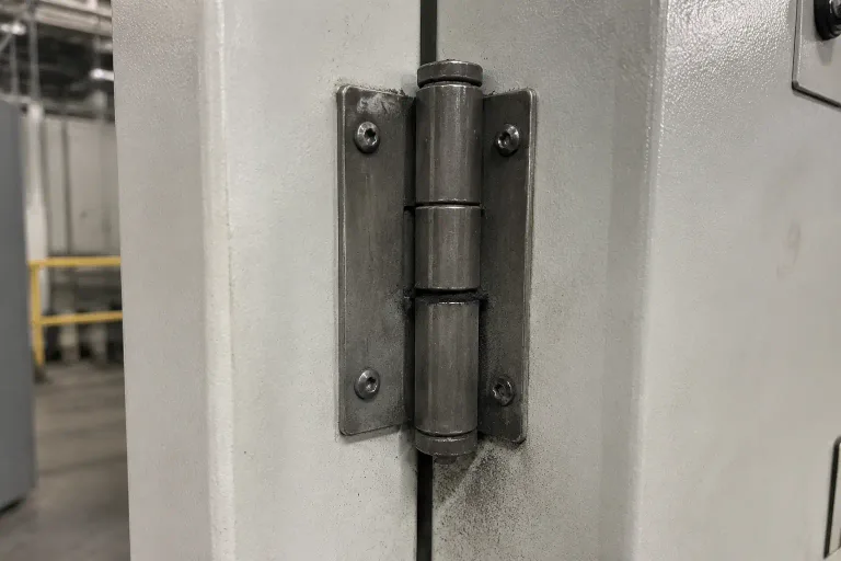
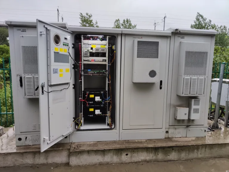
A HTAN é um dos principais fabricantes de dobradiças, pegas e fechos industriais na China.


A Validação do conjunto da dobradiça da porta da máquina A verificação deve ir além de apurar se uma dobradiça solta parece estar correta ou se gira numa bancada de inspeção. A porta concluída pode ainda ceder após a remoção do seu suporte temporário, encravar após a libertação de uma moldura soldada do seu dispositivo de fixação ou deslocar-se após uma junta aparafusada ser finalmente apertada e submetida a carga.
A montagem de referência deve incluir a porta destinada à produção, o caixilho, a estrutura de fixação das dobradiças, os acessórios montados na porta, o trinco ou bloqueio, o dispositivo de restrição de abertura, o estado de acabamento e quaisquer cabos, mangueiras ou ligações elétricas que se desloquem juntamente com a porta. A validação compara, em seguida, a geometria e a função mensuráveis antes e depois das condições de funcionamento que possam alterar o alinhamento.
Este guia explica como preparar esse conjunto, estabelecer uma linha de referência válida, realizar um teste de exposição operacional específico do projeto, repetir as medições e decidir se o resultado justifica a libertação para produção ou se requer medidas corretivas e uma nova amostragem.
Limites de validação
Este artigo valida um conjunto de porta de máquina já instalado. Não substitui a inspeção à entrada do componente de dobradiça solto, a validação do processo do fornecedor, a inspeção do primeiro artigo nem a inspeção contínua da produção.
Se o método de fixação não tiver sido selecionado, comece por Guia para a escolha entre dobradiças soldadas e aparafusadas. A validação da montagem só deve ter início depois de definidas a arquitetura da dobradiça e o método de montagem.
Definir e identificar o conjunto representativo da porta da máquina
Uma dobradiça montada numa pequena placa de ensaio pode demonstrar a rotação básica, mas não reproduz o momento total da porta, a flexibilidade da moldura, a posição do trinco, a elasticidade da montagem, a resistência do cabo, a acumulação de material de acabamento nem a restrição de abertura da máquina de produção.
Antes de realizar os testes, identifique exatamente o que o conjunto representa e associe cada componente relevante à respetiva revisão do desenho ou da especificação.
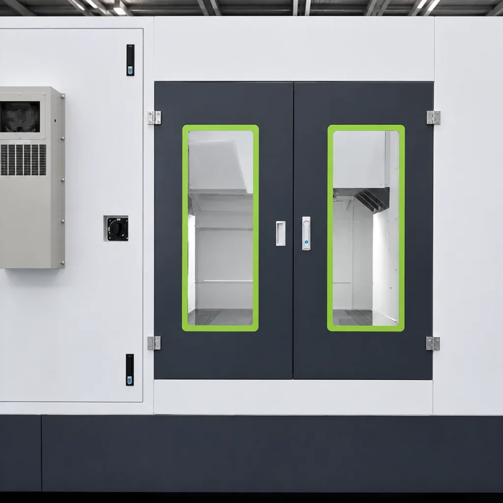
| Elemento de montagem | Representação com vista à produção | Risco em caso de omissão ou substituição incorreta |
|---|---|---|
| Estrutura da porta | Painel, estrutura interna, rebordos, reforço, janelas, rede, isolamento, proteções e tampas amovíveis | A amostra pode não reproduzir a rigidez final, a distribuição da massa ou o centro de gravidade |
| Ferragens para portas | Puxadores, fechos, mecanismos de articulação, peças de IHM, ventiladores, indicadores, atuadores de interbloqueio e acessórios para cabos | A porta testada pode ser mais leve ou ter um equilíbrio diferente do da porta de série |
| Estrutura da máquina | Tubo representativo, placa, flange moldada, extrusão, base de fixação ou abertura estrutural | A deformação da estrutura e o apoio da dobradiça não estão representados |
| Montagem com dobradiças | Condições de soldadura para produção ou elemento de fixação, placa de apoio, inserção, calço, espaçador e padrão de orifícios | O teste verifica a dobradiça, mas não a junta instalada |
| Interface de encerramento | Trava, contra-trava, junta, batente de porta, sobreposição de proteção ou atuador de interbloqueio | A repetibilidade na posição fechada não pode ser avaliada |
| Controlo de abertura | Paragem, fixação, retenção, articulação de torque, corrente, sistema de retenção por cabo ou suporte independente | A dobradiça pode ser sujeita a um curso excessivo não pretendido ou a cargas de impacto |
| Serviços de mudanças | Cabo elétrico, mangueira, fita de ligação à terra, condutor de ligação, conector e circuito de serviço | A resistência ou a interferência no percurso podem alterar o movimento e o alinhamento da porta |
| Condição da superfície | Revestimento, galvanização, mascaramento, acumulação de tinta e áreas de juntas sem revestimento, conforme previsto na produção | As folgas, o atrito e as condições de contacto dos parafusos podem vir a sofrer alterações posteriormente |
O registo de montagem deve indicar o modelo ou o número de peça da dobradiça, o sentido de abertura, o número de dobradiças, o desenho da porta, o desenho da moldura, a versão do trinco, as especificações de montagem, o estado do acabamento e o estado do dispositivo de ensaio.
Caso um componente final não esteja disponível, documente o substituto e explique de que forma este representa a massa, o centro de gravidade, a rigidez, a inércia rotacional, a flexibilidade de montagem, a rigidez do cabo, o comportamento de paragem e o envelope de interferência do componente em falta. Assinale as condições não verificadas Preliminar ou A confirmar.
Colocar o conjunto na sua condição de produção
Não devem ser efetuadas medições de referência formais enquanto a porta estiver parcialmente montada, apoiada temporariamente, imobilizada por um dispositivo de soldadura ou sem os seus acessórios finais. A montagem deve, em primeiro lugar, atingir o estado que se pretende reproduzir na produção.
- Conclua o processo de montagem da dobradiça. Conclua a condição de soldadura especificada ou conclua o procedimento de montagem por aparafusamento e aperto aprovado.
- Permitir que as estruturas soldadas atinjam o estado de inspeção definido. Deixe arrefecer completamente e solte o dispositivo de soldadura ou de alinhamento em questão antes de estabelecer a linha de referência final.
- Acabamento completo para produção. Aplique a tinta, o revestimento, o revestimento metálico, a máscara ou o tratamento de superfície pretendido nos locais onde isso afete a folga ou o assentamento das juntas.
- Instale todo o material de fixação. Adicione janelas, puxadores, peças de fecho, componentes de IHM, cabos, mangueiras, tiras de ligação à terra, isolamento, proteções e tampas.
- Instale as interfaces de encerramento e abertura da produção. Incluir os componentes de fecho, contrafecho, junta, batente, suporte, retentor, dispositivo de retenção e interbloqueio mecânico, sempre que aplicável.
- Retire o suporte temporário da porta. A dobradiça e o caixilho devem suportar a porta representativa sem que qualquer acessório oculte a flacidez ou o movimento das juntas.
- Defina a condição do quadro representativo. Apoie, nivele ou fixe a estrutura conforme definido no plano de validação.
Regra de base: Não considere as medições efetuadas antes da carga final, do aperto final, da libertação do dispositivo de fixação, da aplicação do acabamento ou da remoção dos suportes temporários como a referência formal para fins de produção.
Aplicar a carga total da porta móvel e estabelecer o valor de referência
A carga de ensaio relevante é o conjunto completo que gira com a dobradiça, e não apenas o painel isolado. Registe a massa total em movimento e a localização do centro de gravidade em relação ao eixo da dobradiça. Utilize o Guia de capacidade de carga das dobradiças para portas industriais para determinar as cargas subjacentes e o dimensionamento preliminar das articulações.
Não coloque um peso de ensaio arbitrário sem documentar a sua posição. Massas iguais colocadas a distâncias diferentes do eixo da dobradiça criam momentos diferentes na porta. No caso de portas motorizadas, de movimento rápido ou com restrições de impacto, analise também a distribuição da massa, a inércia rotacional, a velocidade de abertura, a força do atuador, a desaceleração na paragem e possíveis condições de fecho brusco.
Após a instalação completa da carga e a remoção do suporte temporário, efetue medições geométricas e funcionais repetíveis.
| Item de referência | Método de medição ou referência | Por que é importante |
|---|---|---|
| Referência do eixo da dobradiça | Mandril de alinhamento, pino de referência amovível, característica da linha central do cilindro, ponto de referência especificado da lâmina ou trajetória rotacional validada | Fornece uma referência repetível para a deteção do movimento do eixo ou de dobradiças não coaxiais |
| Altura da borda livre | Ponto definido junto ao lado da trava, com a porta numa posição especificada | Revela afundamento, deformação da estrutura ou movimento da montagem |
| Espaço no perímetro | Definiram-se os pontos A, B, C e D em torno da porta fechada | Apresenta torção da porta, movimento angular e fecho irregular |
| Posição de entrada-saída | Plano da porta em relação à abertura da máquina antes do engate do trinco | Identifica o movimento da folha, a resistência da junta ou o excesso de força na travagem |
| Posição do trinco | Trajetória de ataque, posição de combate e movimento de aproximação | Indica se o fecho está a compensar o erro da dobradiça ou do caixilho |
| Alinhamento do interbloqueio | Percurso de entrada do atuador e folga mecânica | Identifica cargas laterais ou desvios posicionais na interface mecânica |
| Ângulo de abertura | Posição da porta em relação ao batente, apoio, encaixe ou dispositivo de retenção especificados | Confirma o envelope de acesso pretendido e o controlo do deslocamento excessivo |
| Força de manobra da porta | Ponto de manuseamento, direção, ângulo da porta, velocidade e temperatura definidos | Deteta encravamento, atrito da vedação, resistência do cabo ou alterações no atrito |
| Binário da dobradiça | Registar apenas nos casos em que seja especificada uma dobradiça de binário ou de atrito | Confirma a função de controlo de posição especificada, sem a confundir com a força geral da porta |
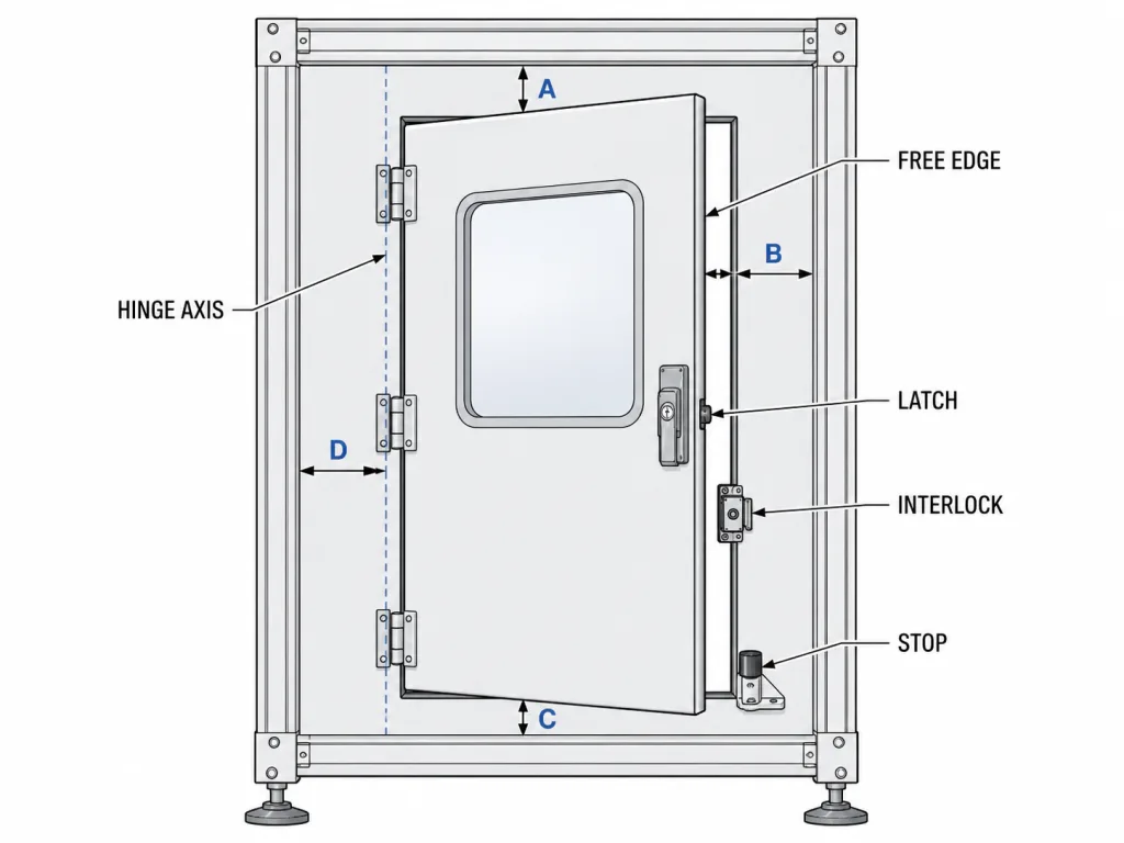
A norma ASME Y14.5 pode fornecer uma terminologia padronizada para pontos de referência, dimensões e tolerâncias geométricas no desenho aprovado. Não define a folga aceitável da porta do projeto, o número de ciclos, a carga, a quantidade de amostras, o instrumento de medição nem os limites de aprovação/reprovação.
Coerência das medições: Utilize a mesma posição da porta, o mesmo suporte da moldura, os mesmos pontos de referência, os mesmos pontos de medição, os mesmos instrumentos e o mesmo método de operação, tanto antes como depois do ensaio. Uma alteração na configuração da medição pode parecer uma alteração na montagem.
Verificar o movimento completo e as interfaces de encerramento
Uma porta não deve ser aprovada apenas com base nas posições totalmente aberta e totalmente fechada. Podem ocorrer encravamentos, tensão do cabo, interferência do cilindro, contacto com a moldura e subida ou descida da porta apenas numa parte do percurso de abertura.
| Posição da porta | Verificar | Possível motivo de preocupação |
|---|---|---|
| Abertura inicial | Libertação do fecho, separação da junta, movimento do cabo e força de separação | Interferência na trava, aderência da vedação, tensão do cabo ou atrito excessivo |
| A meio do movimento | Alterações na força de acionamento, no movimento dos pinos, na folga da estrutura e no movimento vertical da porta | Dobradiças não coaxiais, torção da estrutura, pino dobrado ou calços incorretos |
| Abertura máxima | Interrupção ou manutenção do serviço, acesso ao serviço, reserva de cabos e espaço livre para equipamento adjacente | Deslocamento excessivo, tensão no cabo, impacto na dobradiça ou espaço de manutenção bloqueado |
| Aproximação final | Posição da porta antes de o trinco, a junta ou o bloqueio começarem a encaixar-se | Desalinhamento ocultado pelos acessórios de fecho |
| Totalmente fechado | Repetibilidade da folga, engate do trinco, estado da junta e força de reabertura | Força excessiva na alavanca, compressão excessiva da vedação, encravamento ou desvio da borda livre |
Não é necessário utilizar uma dobradiça de oscilação livre para manter a porta num ângulo arbitrário. Em vez disso, certifique-se de que o batente, o retentor, o dispositivo de retenção, a dobradiça de binário ou o dispositivo de retenção separado especificados controlam a posição de abertura pretendida.
Sempre que um cabo, mangueira, fita de ligação, condutor de ligação à terra ou conector atravessar o lado da dobradiça, certifique-se de que segue um percurso de serviço controlado ao longo de todo o movimento. O elemento móvel não deve afastar a porta da sua trajetória definida nem ficar preso na folha, na moldura, no batente ou no trinco.
O trinco deve encaixar sem que seja necessário levantar, rodar ou empurrar a borda livre para o lado. Registe a posição da porta imediatamente antes do encaixe do trinco, para que a força exercida pelo trinco não oculte eventuais erros nas dobradiças ou na moldura.
Uma verificação do sistema de interbloqueio descrita neste artigo valida apenas a posição do atuador mecânico, a folga e a ausência de cargas laterais. Não valida o circuito de segurança, a função de bloqueio da proteção, a cobertura de diagnóstico nem o desempenho exigido em termos de segurança funcional.
Utilize o ponto de verificação de validação correto para o método de montagem
As medições de aceitação ao nível da porta são semelhantes para conjuntos soldados e aparafusados, mas o ponto de controlo de inspeção correto é diferente.
| Método de montagem | Ponto de verificação para ambiente de produção | Evidências ao nível da montagem |
|---|---|---|
| Dobradiça soldada | Após a soldadura final, o arrefecimento, a remoção do dispositivo de fixação e a soldadura das estruturas circundantes relevantes | Referência do eixo da dobradiça, folgas das portas, posição da borda livre, curso total, alinhamento do trinco e estado visível das soldaduras ou da moldura |
| Dobradiça aparafusada | Após o aperto final, a colocação das calças, a remoção dos apoios temporários e a aplicação de uma carga representativa | Posição da folha, folgas das portas, posição da borda livre, curso total, alinhamento do trinco e sinais visíveis de movimento nas juntas |
Para obter informações sobre o projeto de montagem soldada, o controlo dos dispositivos de fixação e os detalhes relativos ao alinhamento pós-soldadura, utilize o guia da dobradiça da porta da estrutura da máquina soldada.
No que diz respeito aos padrões de parafusos, suporte de fixação, roscas, calços, ajuste e estrutura das juntas, utilize o guia para dobradiças de portas de estruturas de máquinas aparafusadas.
As marcas de referência nos elementos de fixação podem constituir uma prova complementar de movimento relativo visível, mas não confirmam a pré-carga do parafuso nem a integridade total da junta. O processo de aperto gradual, as ferramentas calibradas, o assentamento da junta, o movimento das lâminas, o atrito, o encaixe da anilha e a deformação local devem ser analisados em conjunto.
Executar a exposição operacional específica do projeto
Não existe um ciclo de contagem universal aplicável a todas as portas das máquinas. A condição de validação deve refletir a forma como se prevê que o equipamento seja operado, mantido, transportado e instalado.
| Campo de testes | O que o plano de validação deve indicar |
|---|---|
| Contagem por ciclo ou duração | Requisitos específicos do projeto, com base na frequência de acesso e no regime de funcionamento do equipamento |
| Carga na porta | Massa total em movimento, condição do centro de gravidade e distribuição de massa aplicável |
| Amplitude de movimento | Ângulo de abertura, posição de fecho, condição de paragem e quaisquer posições operacionais intermédias |
| Método de funcionamento | Movimento manual ou motorizado, ponto da alavanca, estado do atuador, velocidade e condições permitidas de batida ou impacto |
| Ambiente | Temperatura, contaminação, humidade, lavagem, poeira ou outras exposições específicas do projeto |
| Lubrificação | Estado inicial, manutenção permitida, especificação do lubrificante e qualquer intervalo de relubrificação |
| Pontos de inspeção | Contagens de ciclo intermédias ou eventos que exijam medições e inspeção visual |
| Critérios de aceitação | Alterações admissíveis na geometria, alterações na força de acionamento, danos visíveis, funcionamento do trinco e alinhamento do bloqueio |
| Incerteza de medição | Capacidade do instrumento e método adequados ao limite de aceitação especificado |
Os dados dos ensaios às dobradiças fornecidos pelo fornecedor podem servir de apoio à análise de engenharia, mas devem identificar o modelo testado, o dispositivo de fixação, a carga, a orientação, a temperatura, o número de ciclos, a velocidade, a lubrificação, os critérios de aceitação, o resultado e o número ou a data do relatório. Os dados gerados com uma orientação de montagem, trajetória de carga ou momento da porta diferentes podem não ser representativos do conjunto da porta da máquina.
Repita as medições de referência após os testes
Não conclua o relatório de ensaio com a afirmação de que a porta “ainda funciona”. Repita as medições iniciais utilizando as mesmas condições da moldura, pontos de referência, posições da porta, ferramentas e método de operação.
| Evidências pós-teste | Comparar com o valor de referência | Possível disposição |
|---|---|---|
| Referência do eixo da dobradiça | Alteração da posição ou da coaxialidade | Verificar se o movimento de montagem, a distorção da estrutura ou o desgaste das dobradiças estão em boas condições |
| Posição da borda livre | Alteração vertical e de entrada-saída | Verificar ou avaliar a flacidez, a deflexão do quadro e o movimento das juntas |
| Lacunas no perímetro | Alterar nos pontos definidos A–D | Verificar se a porta apresenta torção, desvio angular ou se o trinco está a ser puxado em excesso |
| Força de manobra da porta | Alteração ao longo do mesmo intervalo de movimento | Verificar ou inspecionar a fixação, a contaminação, o arrasto dos cabos, o estado das juntas e o atrito |
| Trava e bloqueio mecânico | Percurso de entrada, carregamento lateral e repetibilidade do fecho | Verificar ou rever a posição da dobradiça, a localização do batente, a inclinação da porta ou a interface de fecho |
| Interface de montagem | Movimento visível, atrito, deformação local, estado da soldadura ou movimento do inserto | Aprovação, ação corretiva ou nova amostragem |
| Controlo de abertura | Paragem, posição de repouso, travão, articulação de binário ou posição de retenção | Aprovar ou rever o excesso de curso e a carga dinâmica |
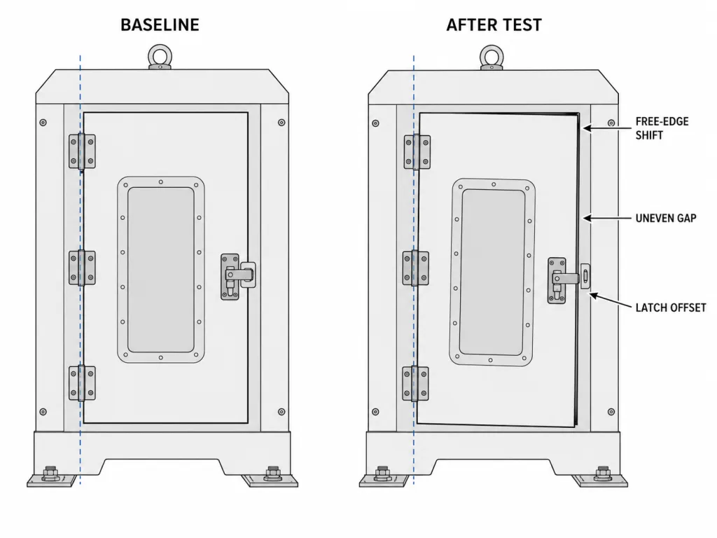
Qualquer alteração medida deve ser comparada com um limite funcional específico do projeto. Uma alteração cosmética na folga pode ser aceitável numa máquina, mas inaceitável quando afeta um fecho, uma vedação, um bloqueio, a sobreposição de uma proteção, a folga de esmagamento ou um componente adjacente.
Verificar novamente a instalação condicional e as exposições dos serviços
Algumas portas das máquinas só alteram de posição após a instalação, o transporte, a manutenção ou a exposição ambiental. Inclua estas verificações apenas quando corresponderem à sequência real de produção ou de manutenção.
| Exposição condicional | Por que razão isso pode alterar a montagem | Repetir após a exposição |
|---|---|---|
| Nivelamento ou fixação de máquinas | A base ou a estrutura podem torcer-se à medida que os suportes e as fixações são ajustados | Abertura da porta, folgas, posição da borda livre, trinco e percurso do bloqueio |
| Transporte ou vibração | As juntas, o movimento da estrutura e a massa montada na porta podem alterar o alinhamento | Interface de montagem, folgas, fecho, cabos e controlo de abertura |
| Remoção e reinstalação de portas | As calças, os orifícios de passagem, os pinos amovíveis ou os elementos de posicionamento podem não voltar à posição original | Referência do eixo, folgas, altura da borda livre e repetibilidade do fecho |
| Substituição da dobradiça no terreno | A geometria de substituição ou a posição de montagem podem diferir da configuração aprovada | Conjunto completo de dados de referência e movimento completo |
| Temperatura ou exposição ambiental | Os materiais, as juntas, os lubrificantes, os revestimentos e as folgas podem reagir de forma diferente | Força de acionamento, folgas, trinco, batente e estado visível da montagem |
| Intervenção de manutenção | A remoção de fixadores, a lubrificação, a manutenção de cabos ou a substituição de componentes podem alterar o sistema | Medidas de referência relevantes e trajetória de movimento |
Decidir se a montagem é aprovada, se requer correção ou se é necessário repetir a amostragem
Uma medição com resultado insatisfatório não significa automaticamente que a dobradiça necessite de uma capacidade de carga superior. O resultado pode ser causado pela porta, pela moldura, pela interface de montagem, pelos mecanismos de fecho, pelos serviços móveis, pelo dispositivo de restrição de abertura ou pela configuração do ensaio.
As medidas corretivas devem identificar o desenho ou processo afetado e determinar se a configuração de ensaio aprovada sofreu alterações.
| Alteração após a validação inicial | Disposição típica |
|---|---|
| Alterações no modelo da dobradiça, na geometria da folha, no pino, na bucha, no desvio ou na orientação | Normalmente, é necessária uma revisão técnica e uma reamostragem representativa |
| Alterações no número de dobradiças, no espaçamento ou na localização dos eixos | Repetir a validação completa da carga, da geometria, do movimento e da interface de fecho |
| Alterações no padrão de parafusos, na ranhura, na placa de suporte, na inserção, no calço ou no processo de aperto | Repetir a validação da montagem por aparafusamento |
| Alterações na localização da soldadura, no estado da soldadura, no dispositivo de fixação, na sequência ou no reforço da estrutura | Repetir a validação após a soldadura e após a remoção do dispositivo de fixação |
| Massa da porta, centro de gravidade, distribuição da massa ou alterações significativas nos acessórios montados na porta | Analisar os dados de carga e repetir os ensaios representativos |
| Alterações na posição do trinco, da contraplaqueta, da junta, do batente, do suporte ou do bloqueio mecânico | Repetir as verificações de movimento completo e de fecho da interface |
| Alterações no traçado de cabos, mangueiras, tiras de ligação ou circuitos de serviço | Repita a revisão completa dos movimentos e das interferências |
| Alterações no acabamento ou no revestimento que afetem o assentamento, o atrito ou a folga | Repita as verificações da linha de base e do movimento afetadas |
| Apenas uma alteração documentada de uma característica estética sem função é permitida | A equipa de engenharia poderá concluir que não é necessário proceder a uma reamostragem completa |
Um desvio só pode ser aceite se estiver em conformidade com um requisito específico do projeto devidamente documentado e com uma disposição autorizada. Não converta um resultado fora dos limites numa nova tolerância informal, uma vez que a porta ainda pode ser fechada à força.
Cenário de engenharia de compósitos: Uma porta de serviço de proteção de uma máquina
Trata-se de um cenário de engenharia hipotético criado para explicar a lógica de seleção. Não se trata de um registo de projeto de um cliente nem de uma declaração relativa a testes de produtos.
Considere uma porta de serviço alta para uma proteção automatizada de uma máquina. A porta inclui uma moldura interior em aço, um painel transparente, um puxador, um mecanismo de fecho, um atuador de interbloqueio mecânico e um cabo que conduz a um componente de controlo montado na porta. Três dobradiças aparafusadas fixam a porta a uma abertura moldada na estrutura da máquina.
A primeira inspeção é realizada enquanto a porta ainda se encontra apoiada num suporte de montagem e antes da instalação do cabo final e do painel de visualização. A porta apresenta-se alinhada e o trinco fecha. Essas medidas são registadas como referência.
Esta não é uma linha de base válida para produção. A montagem está incompleta e o suporte temporário impede que as dobradiças e a moldura suportem todo o momento da porta.
A equipa de validação instala o painel e o cabo finais, conclui o processo de aperto dos elementos de fixação, remove o suporte temporário e posiciona a moldura na sua condição de montagem representativa. Em seguida, são registados a altura da borda livre, as folgas perimetrais, o plano da porta, o percurso do trinco, a força de manobra e a folga do bloqueio.
Após a exposição ao ciclo específico do projeto, a folga superior e a posição do lado do trinco alteram-se. As marcas de referência do elemento de fixação não revelam qualquer rotação evidente, mas observa-se um ligeiro desgaste por atrito na folha superior da dobradiça. Uma vez que as marcas de referência não comprovam a pré-carga, a análise inclui o assentamento da junta, o apoio de reforço, os registos de aperto, o movimento da folha, a conformidade da estrutura e a resistência do cabo.
A ação corretiva altera o suporte superior de apoio e o circuito de manutenção do cabo. Uma vez que estas alterações afetam a interface de montagem e o movimento da porta, o conjunto completo revisto é submetido a novos ensaios, em vez de se aprovar apenas a dobradiça de substituição.
Provas documentais de que a produção pode ser reproduzida
Uma fotografia autografada e a menção “aprovado na montagem” não permitem determinar o que foi testado. O registo deve permitir que os departamentos de engenharia, qualidade e produção, bem como o fornecedor das dobradiças, reconstituam as condições de validação.
| Elemento de prova | Conteúdo obrigatório |
|---|---|
| Identidade da Assembleia | Informações sobre dobradiças, portas, caixilhos, trancas, batentes, acabamentos, montagem, cabos e revisões |
| Estado de preparação para produção | Estado da soldadura ou do aperto concluído, libertação do dispositivo de fixação, estado final, ferragens instaladas e estado dos suportes |
| Carregar configuração | Massa total em movimento, centro de gravidade, orientação e distribuição de massa relevante |
| Registo de referência | Eixo de referência, posição da borda livre, folgas perimetrais, plano da porta, trinco, interbloqueio, ângulo de abertura e força de manobra |
| Exposição operacional | Contagem de ciclos, velocidade, amplitude de abertura, condições ambientais, lubrificação, paragens e manutenção autorizada |
| Medições pós-teste | Valores de referência repetidos e inspeção visual da interface de montagem |
| Exposições condicionais | Nivelamento, fixação, transporte, remoção, reinstalação, substituição ou reprodução das condições ambientais |
| Fotografias | Montagem completa, interfaces de fixação, ferragens de fecho, configuração de medição e alterações observadas |
| Registo de desvios | Requisito, resultado, estado da causa principal, ação corretiva, resolução e decisão de nova amostragem |
| Rastreabilidade | Número ou data do relatório, instrumentos, estado de calibração, inspetor e entidade responsável pela aprovação |
Lista de verificação para a validação do conjunto da dobradiça da porta da máquina
- A dobradiça, a porta, o caixilho, o método de montagem, os acessórios de fecho e as revisões são rastreáveis.
- O conjunto inclui a massa móvel completa, tal como prevista para a produção, e a condição do centro de gravidade.
- A soldadura final ou o aperto dos parafusos é concluído antes de se registar a linha de referência formal.
- As estruturas soldadas são arrefecidas e retiradas do dispositivo de fixação correspondente.
- O acabamento de produção e os componentes montados nas portas já estão instalados.
- O suporte temporário da porta é removido antes das medições de referência.
- O eixo da dobradiça está relacionado com um ponto de referência ou método de medição repetível.
- São registadas a posição da borda livre, as folgas perimetrais, o plano da porta, o percurso do trinco e a força de manobra.
- A porta desloca-se ao longo de toda a amplitude prevista, sem encravamentos nem deslocamento excessivo descontrolado.
- O batente, o retentor, o dispositivo de retenção, a dobradiça de binário ou o dispositivo de retenção especificados controlam a posição de abertura necessária.
- Os cabos, as mangueiras e as ligações de ligação à terra movem-se sem puxar nem ficarem presos.
- O trinco não levanta, não gira nem força a porta para a colocar em alinhamento.
- A interface do bloqueio mecânico é alinhada sem ser considerada como prova de validação da segurança funcional.
- A exposição operacional específica do projeto e os critérios de aceitação estão documentados.
- As mesmas medições de referência são repetidas após o teste.
- As informações relevantes relativas à instalação, transporte, remoção ou exposições ambientais são repetidas sempre que necessário.
- As marcas de referência são utilizadas apenas como prova complementar, e não como prova da pré-carga do elemento de fixação.
- As alterações ao projeto ou ao processo que afetem a configuração aprovada desencadeiam uma revisão técnica e uma nova amostragem, sempre que necessário.
Uma recomendação preliminar identifica uma possível arquitetura de dobradiça. A revisão de engenharia confirma a interface proposta. A aprovação da amostra do componente confirma a evidência de que a dobradiça está solta. A validação da montagem confirma que a porta instalada é representativa. A autorização para produção requer, além disso, desenhos controlados, listas de materiais (BOM), processos de fabrico, métodos de inspeção e controlo de alterações.
Perguntas mais frequentes
Quando devem ser efetuadas as medições de referência das portas das máquinas?
Efetue a medição de referência formal após a conclusão do processo de montagem das dobradiças, quando as estruturas soldadas tiverem arrefecido e tiverem sido retiradas do dispositivo de fixação correspondente, as juntas aparafusadas tiverem sido apertadas definitivamente, o acabamento de produção e os acessórios das portas estiverem instalados, a carga móvel completa estiver presente e o suporte temporário das portas tiver sido removido.
Quantos ciclos deve completar um conjunto de dobradiças da porta de uma máquina?
Não existe um número universal de ciclos para todas as portas das máquinas. O requisito deve ter em conta a utilização do equipamento, a frequência de acesso prevista, a carga total da porta, o ângulo de abertura, a velocidade de movimento, o ambiente, o plano de manutenção e os critérios de aceitação específicos do projeto.
A porta de uma máquina com balanço livre tem de permanecer aberta sem apoio?
A menos que o projeto especifique essa função. Uma dobradiça de movimento livre apenas precisa de se mover ao longo do ângulo de abertura necessário sem encravar. A posição de abertura necessária deve ser controlada pelo batente, pelo retentor, pelo dispositivo de retenção, pela dobradiça de binário ou por um dispositivo de retenção separado, conforme especificado.
As marcas de referência dos elementos de fixação comprovam que uma articulação com dobradiça aparafusada está bem apertada?
Não. As marcas deixadas pelas testemunhas podem indicar um movimento relativo visível, mas não confirmam a pré-carga do parafuso nem a integridade total da junta. Verifique o processo de aperto definido, as ferramentas calibradas, o assentamento da junta, o movimento das lâminas, o atrito, o encaixe das anilhas e a deformação local.
O alinhamento correto do interbloqueio valida o sistema de segurança da máquina?
Não. Esta validação da montagem verifica apenas a posição mecânica do atuador, o percurso de entrada, a folga e a ausência de cargas laterais. Não valida o circuito de segurança, a função de bloqueio da proteção, os diagnósticos nem o desempenho exigido em termos de segurança funcional.
Quando é que é necessário voltar a amostrar um conjunto de porta de máquina?
Normalmente, é necessário proceder a uma nova amostragem quando uma alteração afeta o modelo das dobradiças, o número ou a posição das dobradiças, a estrutura de montagem, o estado das soldaduras, o padrão de parafusos, o reforço do caixilho, a carga total da porta, o centro de gravidade, o fecho, o batente, o bloqueio, o percurso dos serviços móveis, a folga de acabamento ou outra interface funcional validada.
Liberte a Assembleia com base nas provas recolhidas
Um sucesso Validação do conjunto da dobradiça da porta da máquina Não se limita a provar que a dobradiça abre e fecha. Confirma que uma dobradiça específica, uma interface de montagem, uma porta com carga, a estrutura da máquina, o trinco, o batente, o bloqueio, o estado de acabamento e o percurso de movimento e funcionamento funcionam em conjunto numa condição de ensaio documentada.
Se o conjunto passar no teste apenas quando apoiado, fixado, em bruto, parcialmente carregado ou forçado a ficar na posição correta pelo seu fecho, isso significa que não demonstrou a condição de produção pretendida.
Enviar os dados do conjunto da porta da máquina
Envie à HTAN os desenhos das dobradiças e das portas, a massa total em movimento, a localização do centro de gravidade, a secção da moldura, a estrutura de montagem, a posição do trinco ou do bloqueio, o ângulo de abertura, a condição de paragem, o percurso dos cabos, o estado de acabamento, a exposição operacional prevista e os critérios de aceitação específicos do projeto.