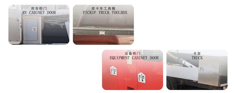
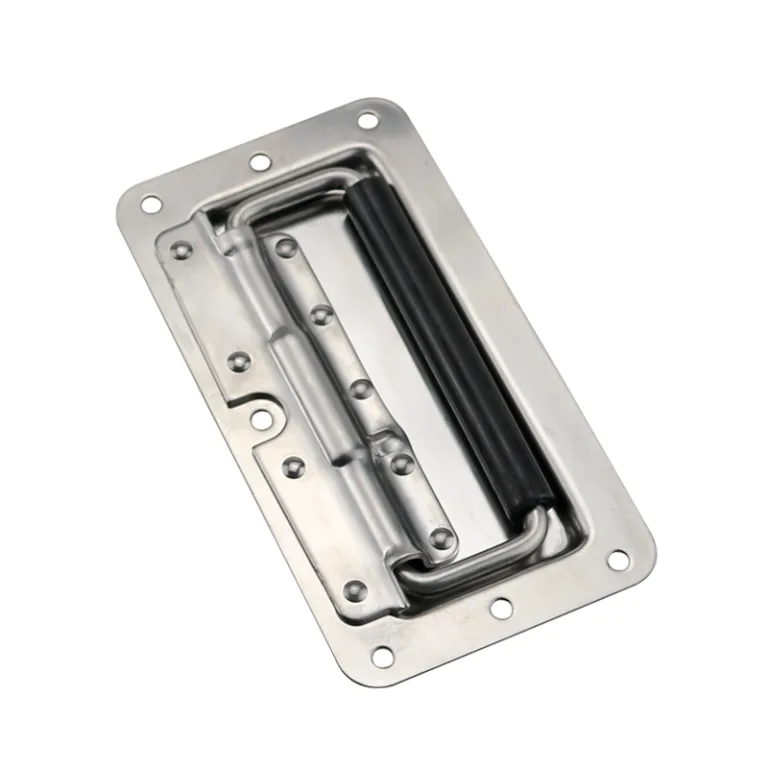
HTAN is one of the leading manufacturers of industrial hinges, handles and latches in China.


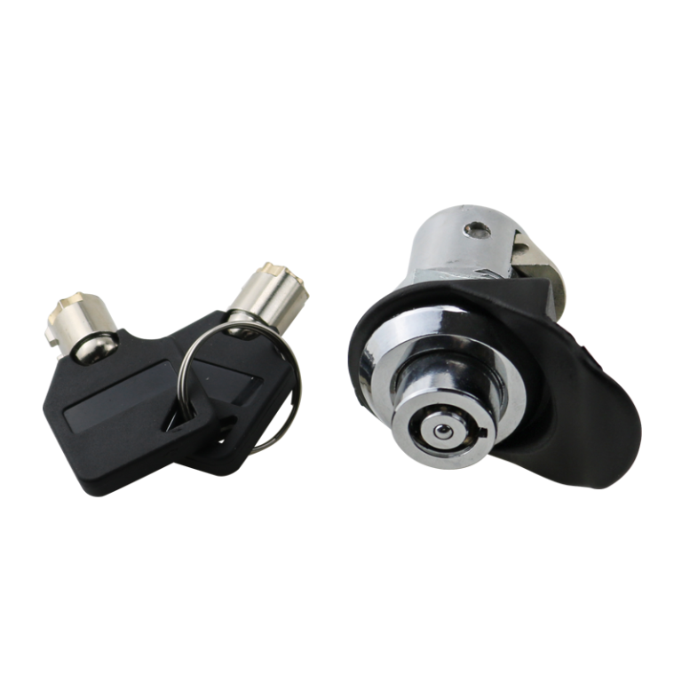
Compression Latches differ fundamentally from standard Cam Latches by their ability to provide a 3mm–6mm axial stroke after closing. This stroke generates a controlled Preload, forcing the gasket into its effective compression range (20%–40%), thereby ensuring compliance with IP65/66 and NEMA 4/4X standards. This active compression mechanism is critical for preventing sealing failures in industrial enclosures, which are typically caused by insufficient compression, vibration loosening, and material creep.
Four Major Engineering Root Causes of Sealing Failure
Sealing is not the result of a single component but a system balance. In field applications, the following factors are the primary causes of leakage.
Compression Set Deviation from Effective Range
Gaskets (e.g., EPDM or PU foam) must be compressed to a specific percentage to generate the rebound force necessary to block liquids.
- Under-compression (<15%): Fails to fill microscopic irregularities in the door panel, creating capillary siphon channels.
- Over-compression (>50%): Exceeds the material’s yield limit, leading to Permanent Set and loss of long-term rebound capability.
- Reference Standard: ASTM D395 or ISO 815 (Standard Test Methods for Rubber Property—Compression Set).
Uneven Pressure Distribution
Single-point or sparse locking points cause corner warping on the door panel. Clamping force decays between locking points, causing the gasket to delaminate from the cabinet body.
Fastener Loosening Under Vibration
During equipment operation or transport, vibration causes the pawl of non-locking latches to slip. Once preload is lost, the sealing interface fails immediately.
- Reference Standard: IEC 60068-2-6 (Vibration Test); MIL-STD-810 (Environmental Engineering Considerations).
Environmental Creep and Aging
Thermal Cycling causes material expansion and contraction. If the latch lacks stroke compensation capabilities, gaps formed during low-temperature contraction will lead to leakage.
Working Mechanism of Compression Latches: From “Locking” to “Preloading”
The core value of a compression latch lies in separating the “positioning” and “compressing” actions.
Mechanical Motion Decomposition
- Rotation Phase: The pawl rotates behind the door frame, completing the physical obstruction (positioning).
- Compression Phase: Continued operation of the handle/tool uses a cam or thread structure to pull the pawl axially toward the door panel.
- Result: Generates an axial displacement (typically 3mm–6mm), actively eliminating the door gap.
Engineering Value of Preload
- Anti-Vibration: High preload increases friction between the pawl and the frame. Combined with mechanical Over-center design, this prevents loosening from vibration.
- Tolerance Compensation: Axial stroke covers manufacturing tolerances, coating thickness variations, and gasket thickness decay due to aging.
Benchmarking International Standards: IP and NEMA Compliance
Procurement must map latch performance to the target enclosure protection rating.
IP Protection Rating (IEC 60529)
- IP65 (Dust tight/Water jets): Compression latches eliminate micro-gaps, preventing dust intake due to negative pressure and resisting low-pressure water jets from all directions.
- IP66/67 (Powerful jets/Immersion): Requires the latch to provide higher and more uniform Clamping Force. Multi-point compression locking is typically recommended.
NEMA Types (NEMA 250 / UL 50E)
- NEMA 4/4X (Outdoor/Corrosion Resistant): Requires latches to not only seal but also feature Stainless Steel (SS304/316) construction and UV-resistant gaskets, passing the Hose-down test.
- NEMA 12 (Indoor/Dust & Oil): Focuses on the anti-leakage capability of the gasket-latch interface.
Technical Comparison: Compression Latches vs. Standard Cam Latches
| Comparison Dimension | Standard Cam Latch | Compression Latch | Procurement Decision Guide |
| Motion Trajectory | Rotation Only | Rotation + Axial Pull | Mandatory for Outdoor/Waterproof |
| Sealing Capability | Uncontrolled | Active compression; Highly controlled | Recommended for IP54+ |
| Vibration Resistance | Poor; Prone to loosening | Excellent; Features Preload/Anti-vibration | Mandatory for Mobile Equipment |
| Tolerance Tolerance | Sensitive | Forgiving; Features stroke compensation | Best for average sheet metal tolerance |
| Cost | Low | Medium/High | Evaluate based on TCO |
Supply Chain Risk Control: Evidence from the Field (VoC)
Analyzing real-world feedback reveals that sealing failure is often due to supply chain omissions rather than design flaws. The following case study highlights critical procurement checkpoints.
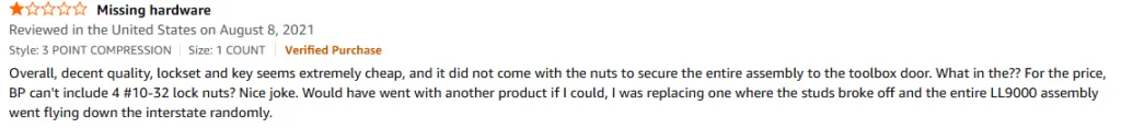
Case Study Analysis: Why “Small Parts” Cause Catastrophic Failure
Based on the verified user feedback shown above, we identify two critical failure modes in budget-grade latches:
Missing Vibration-Proof Hardware
- The Issue: The user explicitly notes the product “did not come with the nuts to secure the entire assembly,” specifically missing #10-32 lock nuts.
- Engineering Consequence: Without Nylon Insert Lock Nuts (Nyloc), standard nuts will back off under vibration (referenced as “flying down the interstate”). A loose latch body equals zero compression force, instantly voiding the IP rating.
- Procurement Action: Verify BOM includes “Installation Hardware Kit” and specify ANSI/ASME B18.16.6 (Nyloc Nuts).
Material Tensile Strength Failure
- The Issue: The review mentions “studs broke off” during transit.
- Engineering Consequence: This indicates the use of low-grade Die-Cast Zinc with internal porosity. It cannot withstand the shear forces generated by a heavy vehicle on a highway.
- Procurement Action: For mobile or heavy-duty applications (NEMA 4), specify Stainless Steel (ASTM A240 Grade 304) bodies. Do not compromise on material grade for high-vibration environments.
Key Selection Parameter Checklist & Calculator
When issuing an RFQ, correct sizing is non-negotiable.
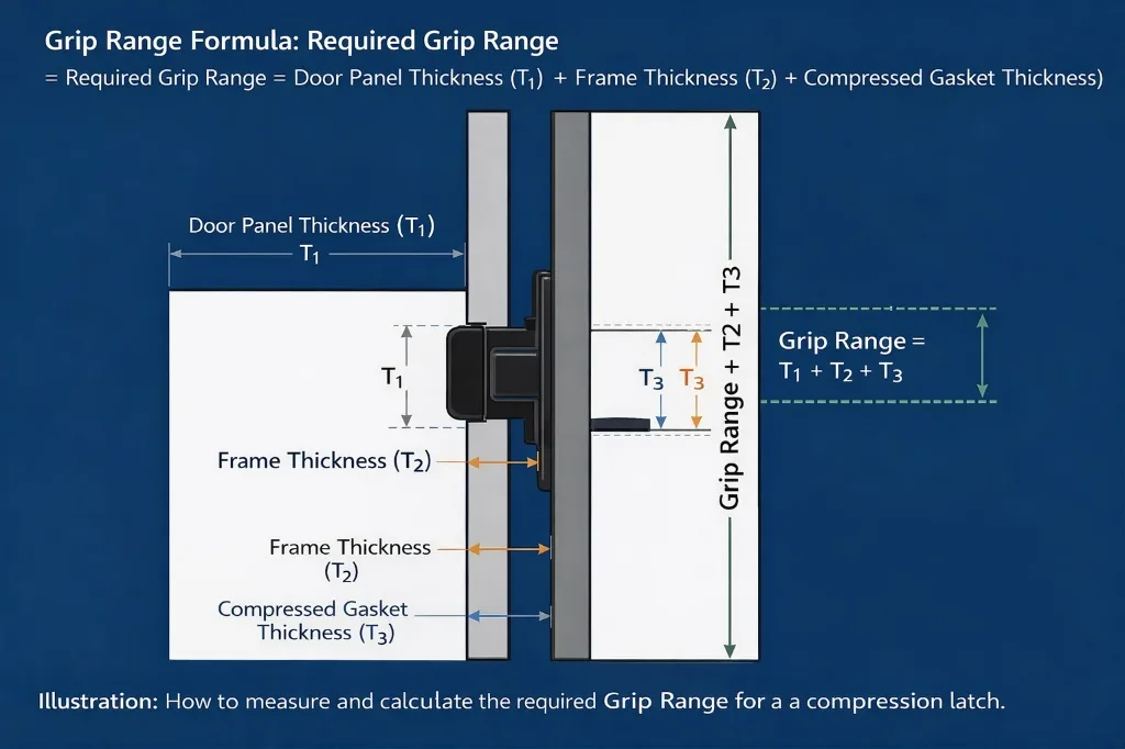
The Grip Range Formula
To ensure the latch engages correctly, calculate your required Grip Range using this logic:
Specification Checklist
- Compression Stroke: Recommended value ≥ 3mm.
- Max. Static Load: Verify tensile strength (e.g., 400N vs 1000N) based on door weight.
- Cutout Dimensions: Confirm industry standard cutouts for future maintenance.
- Environmental Adaptability:
- Gasket Material: EPDM (Standard) vs. Silicone (High Heat).
- Finish: Black Powder Coat vs. Passivated SS316.
SOP for Installation and Verification (How-to Guide)
To ensure theoretical performance translates to field performance, follow this Standard Operating Procedure.
Pre-Installation Check
- Deburring: Ensure installation holes are free of burrs to prevent puncturing the latch’s integrated O-ring.
- Hardware Prep: Locate the Nyloc nuts identified in the BOM. Do not use standard nuts.
Torque Control
- Use a calibrated torque wrench. Refer to ISO 6789 guidelines.
- Warning: Over-tightening causes body deformation; under-tightening causes leakage.
Adjusting Engagement Depth
- Close the door.
- Adjust the regulation screw until the pawl merely touches the frame.
- Tighten an additional 2 full turns to set the required Preload.
Field Verification (The “Paper Test”)
- Clamp a sheet of standard A4 paper in the seal.
- Lock the latch.
- Pass Criteria: The paper cannot be easily pulled out without tearing, and shows a distinct, continuous indentation line.
Conclusion
Compression Latches are not simple fasteners; they are core execution components of the sealing system. By providing controlled Axial Preload, they solve pain points that traditional latches cannot address: tolerance compensation, vibration resistance (as seen in the interstate failure case), and maintaining constant compression ratios.

Anson Li
文章: 595RELATED POSTS
Cam Latch Applications in Industrial Equipment: A Complete Guide
Don’t Ruin Your Chassis: The Engineer’s Guide to Mounting Heavy-Duty Folding Handles
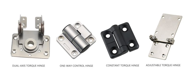
Position-Control Hinges: A Guide to Selection, Torque & Applications
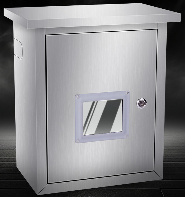
Outdoor Cabinet Cam Locks: Applications and Advantages
China Hinges Manufacturer A Comprehensive Guide for Purchasing