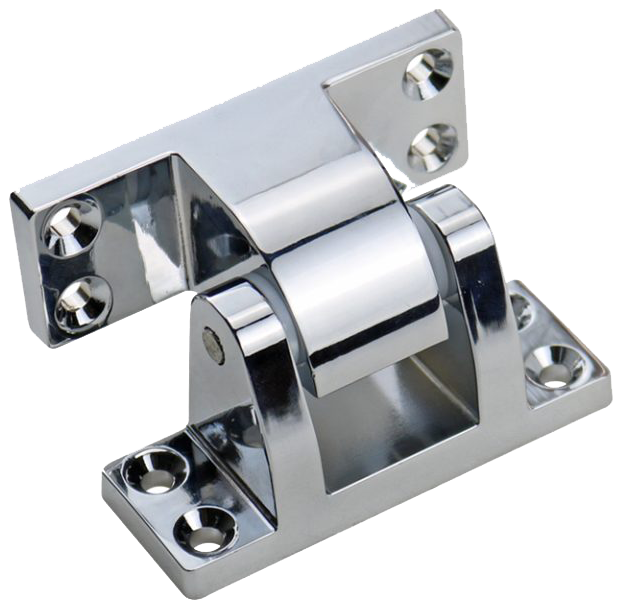
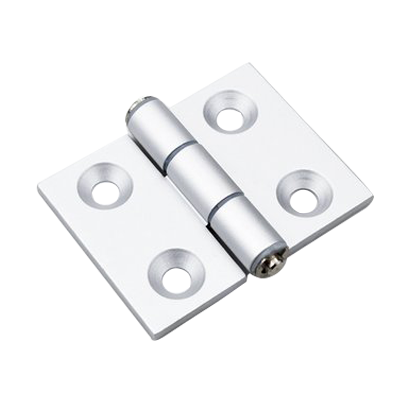
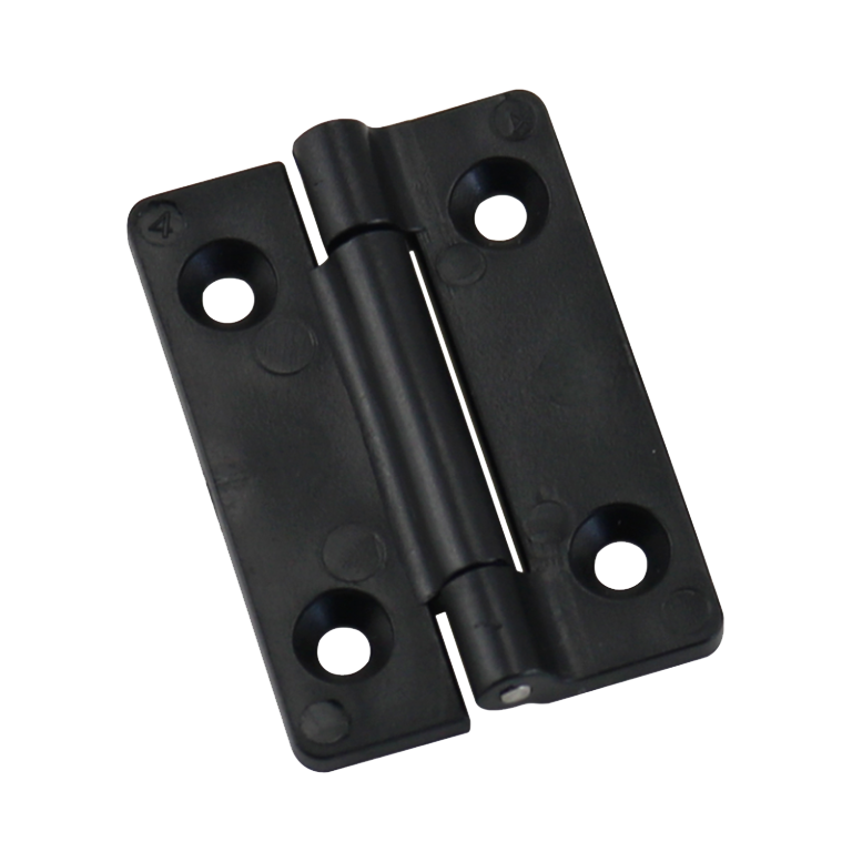
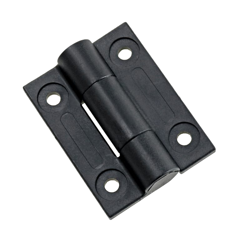
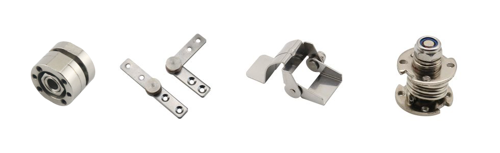
Industrial hinges, handles and latches for OEM equipment.
- +86 13720060320

How to Choose the Right Industrial Hinge
Start with the required motion and installed geometry—not a familiar hinge shape.
A door that only needs to swing, a lid that must hold at intermediate angles, a guard that must lift off for service, and a panel that must return automatically do not require the same hinge mechanism. Their weight may be similar. Their hinge requirements are not.
Knowing how to choose the right industrial hinge begins with the complete moving assembly: its loaded mass, center of gravity, opening behavior, mounting structure, removal method, available clearance, and operating environment. Those inputs should narrow the hinge family before a supplier model is selected.
The Moving Panel Comes First
A hinge does not carry an isolated number from a spreadsheet. It controls a physical assembly. Start with the production-intent door, lid, cover, guard, or panel, including the hardware and accessories that move with it.
A sheet-metal door may gain meaningful load from a window, insulation, lock rods, handles, cable carriers, mounted controls, gas springs, or internal brackets. A top-opening lid may have a moderate mass but a long center-of-gravity arm. A safety guard may be light yet require frequent removal, a defined open position, and dependable alignment with an interlock switch.
| Project Input | What Must Be Defined | Why It Changes Hinge Selection |
|---|---|---|
| Moving assembly | Door, lid, guard, cover, hatch, access panel, or other moving structure | Different assemblies create different axis, access, and support requirements. |
| Loaded mass | Complete moving mass, not only the bare panel | The hinge must work with the real assembly and its load path. |
| Center of gravity | Distance and direction from the proposed hinge axis | The same mass can produce a very different moment when the offset changes. |
| Orientation | Vertical door, horizontal lid, inclined panel, or changing equipment orientation | Gravity assists, resists, or redirects motion differently. |
| Required behavior | Free swing, position holding, indexing, automatic return, controlled removal, or concealed motion | This normally eliminates most hinge families immediately. |
| Travel and stop | Opening angle, required service position, stop location, and nearby interference | The hinge may fit when closed but collide before the required opening angle. |
| Mounting structure | Panel thickness, frame section, reinforcement, weld access, rear fastener access, and allowable cutouts | The available structure determines which attachment and axis geometries are practical. |
| Environment | Moisture, washdown, chemicals, dust, temperature, vibration, impact, and cleaning process | Leaf material alone cannot define the suitability of the complete hinge assembly. |
Do not freeze the hinge location while these inputs are still based on an empty enclosure or an early cosmetic model. A small shift in mounted equipment can move the loaded center of gravity enough to change opening force, door sag, lid balance, or the load carried by each hinge.
Required Motion Narrows the Hinge Family
The first useful hinge question is not “Which material is strongest?” It is “What motion must the assembly produce?” A conventional rotating hinge, a torque hinge, a detent hinge, a spring hinge, and a lift-off hinge can share a similar envelope while performing different jobs.
Free Rotation
Use a free-rotating family when the operator, a separate stay, or another mechanism controls the panel. The hinge mainly establishes the axis and transfers load.
Position Holding
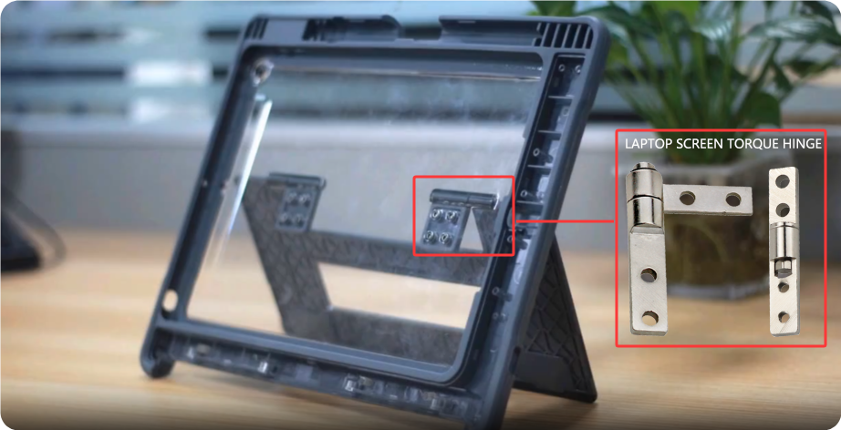
A torque or friction hinge can resist motion through part or all of the travel. Selection depends on the required torque-angle behavior, not only a single nominal torque value.
Defined Positions
A detent or positioning hinge is appropriate when the panel should index into repeatable angular positions. The detent angle, engagement feel, release force, and wear behavior are project inputs.
Automatic Return
A spring hinge can bias a door or flap toward an open or closed position. The return function does not by itself define final closing force, latch engagement, or safe motion.
Planned door removal and concealed installation introduce separate access and mounting constraints. Review those constraints after the required motion has been defined.
Do not combine functions by assumption. A hinge that provides friction may not provide a positive stop. A return spring may not hold a lid safely open. A removable pin may not create a controlled lift-off service procedure. State each required behavior separately.
Load Path Before Catalog Capacity
Door weight is only one part of the load case. The hinge axis, center of gravity, number and spacing of hinges, mounting stiffness, latch condition, and external handling loads determine how that weight reaches the hinge and the surrounding structure.
For an initial static model, the gravity moment about the hinge axis can be expressed as:
M = W × e
- M — moment about the hinge axis.
- W — gravitational force from the complete moving assembly.
- e — perpendicular distance from the hinge axis to the loaded center of gravity.

This is a general mechanics relationship, not a catalog rating and not an allowable design limit. A wide door can create a larger moment than a heavier but narrower door. A horizontal lid changes the gravity relationship through its travel. An operator pulling on the far edge can add a load that the static weight model does not include.
Hinge spacing also matters. Closely spaced hinges provide less resistance to door twisting than hinges distributed over a larger supported height, but increasing spacing only helps when the door and frame can transfer the reactions without local distortion. Adding a third hinge does not guarantee equal sharing. Misalignment can cause one hinge to bind while another carries more load.
A supplier load number is meaningful only with its test basis. Ask whether it applies to one hinge or a pair, the mounting fixture, pull direction, load point, hinge orientation, duration, allowable deformation, and whether the value is a working, proof, ultimate, or cyclic result.
Use the industrial hinge load and leaf-thickness guide when the project has reached detailed structural sizing. For unusually large doors, covers, or impact loads, continue with the heavy-duty hinge selection guide, which covers structural demand, attachment, frame stiffness, and service conditions in greater detail.
Mounting Geometry Sets the Available Families
The desired hinge may not fit the available section. Before comparing models, draw the closed and fully open positions with the proposed hinge axis, door edge, frame return, seal, fasteners, weld zone, and nearby hardware.
Surface-Mounted Hinges
External leaves keep the axis and fasteners accessible and can simplify installation, adjustment, and replacement. The tradeoff is projection outside the enclosure, exposure to impact or tampering, and possible interference with adjacent equipment, packaging, or aisle clearance.
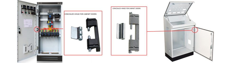
Concealed Hinges
An internal hinge protects the hardware and cleans up the outside surface, but the door edge usually follows a more constrained path. A hinge that fits in the closed model may pull the door into the frame return, compress the seal unevenly, or limit the service opening angle. Internal access for fasteners, adjustment, and replacement must remain possible.

Welded or Bolted Attachment
Weld-on hinges can create a direct structural connection when the base materials and welding process are suitable. They also place alignment under the control of fixturing, weld sequence, heat input, and post-weld distortion. Bolt-on hinges allow removal and adjustment, but need usable fastener access, adequate edge distance, a stable seating surface, and a retention method appropriate to the operating environment.
Slots and shims may help assembly adjustment. They do not repair a weak frame or an unstable load path. Likewise, a thick hinge leaf cannot prevent a thin unsupported panel from dimpling around the fasteners.
The industrial cabinet door hinge guide continues the decision through frame returns, seals, latches, clearances, and complete door construction.
Access and Removal Change the Mechanism
Some doors are removed only during factory assembly. Others must come off during routine filter replacement, machine cleaning, tool access, or module service. Those are different requirements.
A fixed hinge may be the better choice when continuous retention, controlled alignment, security, and cable protection are more important than rapid removal. A removable or lift-off hinge may reduce service steps when the door can be supported, lifted in a defined direction, and stored safely.

- Is there enough vertical or axial clearance to disengage the hinge?
- Can the operator support the door before the last hinge disengages?
- Will a seal, latch, bonding strap, cable, or interlock prevent removal?
- Could vibration or lifting from the door edge cause unintended separation?
- Must the door return to the same alignment without readjustment?
For detailed guidance on lift clearance, handing, accidental disengagement, and repeat installation, see the removable and fixed hinge comparison.
Material Is a System Decision
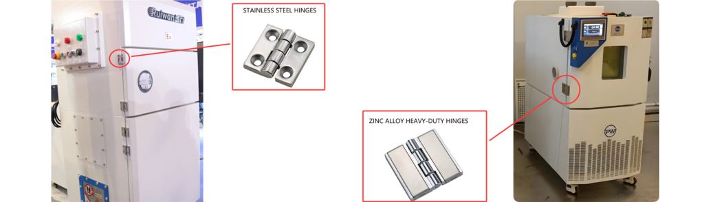
“Stainless steel hinge” is not a complete environmental specification. The leaf may be stainless while the pin, washer, bushing, spring, retaining ring, or mounting fastener uses a different material. A coating may protect visible surfaces while cut edges, welds, threads, or contact zones remain vulnerable.
Define the actual exposure before choosing the material system:
- Dry indoor equipment: corrosion demand may be modest, but wear, lubrication, dust, and appearance can still matter.
- Outdoor enclosures: rain, condensation, pollutants, ultraviolet exposure, and trapped moisture affect the complete assembly.
- Washdown equipment: water direction, detergent, cleaning temperature, drainage, and crevices can be more important than a generic “waterproof” label.
- Chemical or chloride exposure: the chemical concentration, contact time, rinse cycle, temperature, and deposits must be known before comparing stainless grades or coatings.
- Temperature extremes: lubricant behavior, polymer bushings, spring output, clearance, and thermal expansion may change even when the metal retains adequate strength.
Also review material compatibility with the door and frame. Dissimilar metals, conductive paths, coating damage around fasteners, and wet crevices can create local problems that a material name alone does not predict.
Environmental rating and enclosure sealing are separate questions. A corrosion-resistant hinge does not by itself establish an enclosure ingress-protection level. Seal compression, door stiffness, latch distribution, openings, assembly tolerances, and complete-enclosure testing remain part of the enclosure design.
How to Choose the Right Industrial Hinge Family
Use the required behavior to choose the first mechanism family. Then test that choice against the load path, mounting geometry, access needs, and environment. The table is a starting path, not a substitute for a supplier drawing or installed sample.
| Primary Project Need | Likely Hinge Family | What Must Still Be Confirmed |
|---|---|---|
| Simple rotation with a separate latch, stay, or operator control | Conventional fixed-axis industrial hinge | Load path, hinge spacing, axis position, opening angle, mounting structure, and wear interface |
| Panel must remain at intermediate angles | Torque or friction hinge | Torque through the full angle range, direction, number of hinges, temperature, cycle retention, and complete-panel behavior |
| Panel must stop at repeatable angular positions | Detent or positioning hinge | Detent angles, engagement and release force, play, wear, and whether a positive external stop is still required |
| Door or flap must return toward open or closed | Spring hinge | Spring direction, return torque, closing speed, latch engagement, pinch risk, and output after cycling |
| Door must be removed without removing normal fasteners | Lift-off or removable hinge | Handing, extraction direction, lift clearance, accidental disengagement control, handling method, and repeat alignment |
| Hardware must remain inside the enclosure | Concealed hinge | Door-edge sweep, frame interference, seal path, internal access, opening angle, and adjustment method |
| High structural demand with direct attachment to a steel frame | Heavy-duty external or weld-on hinge | Actual reactions, base materials, weld procedure or fastener joint, frame stiffness, distortion control, and serviceability |
| Installation requires replacement, shimming, or field adjustment | Bolt-on hinge with defined adjustment features | Rear access, slot direction, seating surface, clamp load, retention, edge distance, and final locked position |
A project can require more than one behavior. For example, a removable access door may also need a concealed exterior and a detent at the service angle. That does not mean three catalog hinges should be combined. It means the requirements need to be prioritized and reviewed against available integrated mechanisms or a separate door-control device.
When no standard family satisfies the motion, envelope, mounting, and environment at the same time, the next step is not to select the closest catalog shape and hope that validation will correct it. Revise the door architecture, separate functions between components, or discuss a project-specific hinge configuration.
Why the Right Type Can Still Fail
A designer selects two stainless steel external hinges with a catalog load number above the door weight. The CAD model clears, both leaves sit on flat surfaces, and the door opens during bench assembly. After the internal display, lock rods, and wiring are installed, the far edge drops and the door rubs the lower frame return.
The hinge family is not necessarily wrong. The loaded center of gravity moved outward, the frame twists near the upper mount, and the two mounting pads are not coplanar after welding. One hinge binds while the other carries more of the door reaction. Replacing the hinges with a larger catalog model may reduce local stress, but it does not correct the frame or alignment.
This is an illustrative engineering scenario, not a customer project record or product test claim.
Evidence from a nominally correct but failing assembly often includes:
- Door-edge sag that changes when the latch is released.
- Unequal witness marks or wear at the upper and lower hinge.
- Opening force that changes abruptly through the travel.
- Fasteners that remain tight while the surrounding panel deforms.
- A door that moves freely before final frame welding but binds afterward.
- Acceptable single-hinge samples but poor behavior when two hinges are installed on a flexible assembly.
Corrective work should follow the observed load path. Possible actions include moving the hinge axis, increasing hinge spacing, reinforcing the frame, correcting the mounting datums, controlling weld sequence, relocating dense door hardware, separating the stop function from the hinge, or choosing a family with the required motion behavior. Do not treat hinge size as the only available correction.
What the Installed Sample Must Confirm
A loose hinge sample can confirm basic dimensions, finish, and mechanism feel. It cannot prove that the selected family will behave correctly in the final assembly. Use the production-intent moving panel, frame, hinge quantity, mounting method, latch, stop, seal, cables, accessories, and representative load distribution.
| Installed Check | Evidence to Record | Reject the Selection If |
|---|---|---|
| Axis alignment and closed fit | Hinge centerline relationship, mounting-datum condition, door gaps, seal contact, and free movement before forcing the latch | The assembly binds, springs back, or depends on the latch to pull the door into alignment |
| Full travel | Opening angle, door-edge sweep, stops, cables, nearby hardware, and operator hand path | The panel contacts the frame, seal, latch, cable, adjacent panel, or equipment before reaching the required service position |
| Required motion | Free swing, holding angle, detent engagement, return direction, or removal action through the complete travel | The installed behavior differs from the motion requirement used to select the hinge family |
| Loaded response | Door sag, lid drift, opening force, reaction at the stop, and changes after production-intent accessories are installed | Alignment or motion changes materially between the empty and loaded assembly |
| Mounting structure | Panel deflection, frame movement, fastener seating, weld condition, and witness marks around the hinge base | The hinge remains intact but the supporting structure yields, cracks, loosens, or distorts |
Repeat operation long enough to expose changes in play, torque, noise, return action, retention, fastener condition, or door position under the project-defined duty. The number of operations, motion rate, load, temperature, vibration or impact condition, measurement method, and acceptance limits remain project-specific. A frequently serviced machine guard and a rarely opened outdoor enclosure do not share one universal cycle target.
A preliminary recommendation identifies a likely family. Engineering review checks the application inputs and supplier drawing. Sample approval confirms the production-intent assembly under defined conditions. Production approval also depends on repeatable materials, tolerances, welding or fastening, and assembly control. These states should not be treated as interchangeable.
Send the Application, Not Only a Hinge Photo
Provide the moving-panel drawing, loaded mass, center-of-gravity location, required motion, opening angle, hinge quantity and spacing, mounting sections, removal needs, environment, expected duty, and available envelope. These inputs allow a project-specific model discussion without turning a catalog appearance match into an unsupported recommendation.
FAQ
A heavy door does not automatically point to one hinge type. Define the loaded mass, center-of-gravity offset, hinge spacing, frame stiffness, opening behavior, attachment method, impact loads, and service environment. A heavy-duty external, weld-on, bolt-on, bearing-supported, or project-specific hinge may be appropriate, but the installed load path must be reviewed before choosing a model.
No. Door weight does not show the center-of-gravity distance from the hinge axis, dynamic handling loads, hinge spacing, mounting stiffness, required motion, or environmental exposure. Two doors with the same weight can create different hinge reactions and different operating behavior.
Not automatically. Outdoor suitability depends on the complete hinge assembly, including the pin, washers or bushings, springs, retainers, fasteners, surface condition, drainage, crevices, dissimilar-metal contact, pollutants, and maintenance. The stainless grade and finish must be matched to the actual exposure.
Not predictably. Additional hinges can improve support when the door, frame, mounting datums, and hinge centerlines share load as intended. Misalignment or frame flexibility can cause one hinge to bind or carry a disproportionate reaction. The complete assembly must be checked rather than dividing the load equally by the number of hinges.
Choose a removable arrangement when planned service requires the door to come off and the assembly provides a safe extraction direction, sufficient clearance, controlled door support, cable or strap disconnection, protection against accidental disengagement, and repeatable reinstallation. Convenience alone is not enough.
Knowing how to choose the right industrial hinge means reaching one consistent answer from the required motion, loaded geometry, mounting structure, access method, environment, and installed sample. The supplier drawing and sample should confirm that decision—not replace it.