HTAN is one of the leading manufacturers of industrial hinges, handles and latches in China.


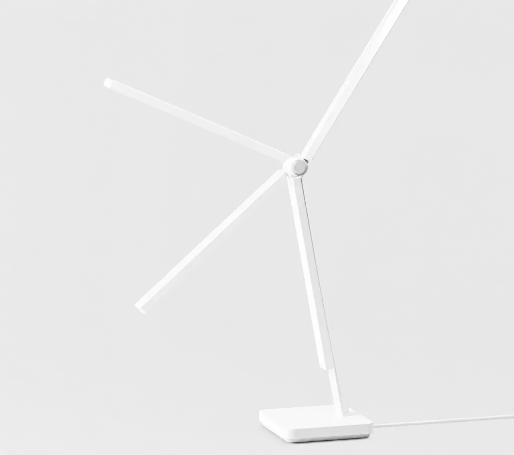
Two lamp heads can weigh the same and still need different hinge torque. Move the center of gravity farther from the pivot and the holding moment rises. Put the same head on a longer downstream arm and the elbow joint sees a different load again. For torque hinges for table lamps, the useful starting point is not lamp-head weight by itself. It is the moment created around each joint through the lamp’s working angles.
That distinction matters in adjustable desk lamps, task lights and compact work-light arms. A hinge that is too weak allows the head to drift. A hinge that is much stronger than necessary can make adjustment heavy, transfer more reaction into thin brackets, or move the lamp base before the joint rotates.
This page stays on that OEM design problem. In lighting hardware catalogs, a position-holding joint may also be described as a table-lamp friction hinge; the useful specification is still the torque behavior around the actual pivot, not the label alone. For a broader explanation of torque-hinge types, directionality and general selection, use the torque hinge selection guide. Here, the lamp arm and its joints are the system being designed.
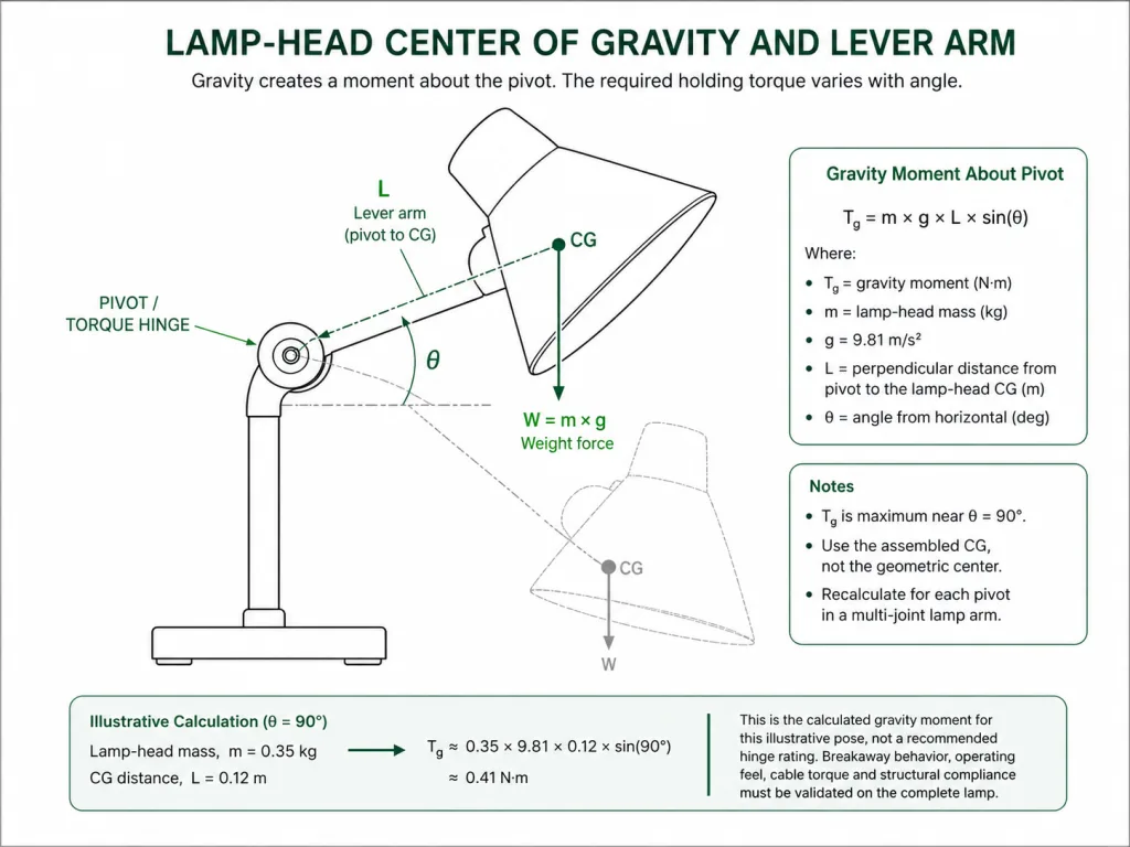
The Lamp Head Creates a Moment
A torque hinge resists rotation around its own axis. The load that tries to rotate a lamp joint is therefore a moment, not simply a mass value printed on a drawing.
For a simplified lamp head rotating in a vertical plane about a horizontal pivot, the static gravitational moment can be estimated from the head mass, gravity, the distance from the pivot to the assembled center of gravity, and the angle of that center-of-gravity line relative to vertical.
Static starting point:
Tg = m × g × L × sin(θ)
where Tg is the gravity moment about the joint, m is the downstream mass, g is gravitational acceleration, L is the pivot-to-CG distance, and θ is the angle between the pivot-to-CG line and vertical.
This is a general mechanics relationship, not an HTAN product rating and not a final production torque value. It assumes gravity is acting in the adjustment plane. If the joint axis is vertical, gravity does not create the same rotational moment around that axis; cable resistance, bearing friction, user input and other loads may become more important.
Illustrative calculation: if a lamp-head assembly has a mass of 0.35 kg, its assembled center of gravity is 0.12 m from the pivot, and the pivot-to-CG line is horizontal (θ = 90°), the gravity moment is approximately 0.35 × 9.81 × 0.12 = 0.41 N·m. That 0.41 N·m is the calculated gravity moment for this example pose, not a recommended hinge rating. Breakaway behavior, running torque, cable effects, production variation and complete-lamp validation still matter.
The center of gravity must represent the assembled moving part. A metal shade, LED board, heat sink, lens, decorative cover, sensor and cable mass can shift it away from the geometric center of the lamp head.
Start With the Highest Gravity Moment
The lamp does not load the hinge equally at every angle. When the center of gravity lies nearly below the pivot, the gravity moment around that joint can be small. As the lamp head or downstream arm moves toward a position where the center-of-gravity offset becomes more horizontal, the moment increases.
For the simplified formula above, the gravity term reaches its maximum when the pivot-to-CG line is perpendicular to gravity. That is why a lamp can appear stable near one end of its travel and then begin to sag as it approaches another working position.
Do not choose the hinge from the most convenient pose in the CAD screenshot. Review the complete intended adjustment range and identify the position that creates the largest moment at each joint. Mechanical stops can reduce the required range if the lamp never needs to enter a more demanding angle.
One Lamp, Several Pivot Loads
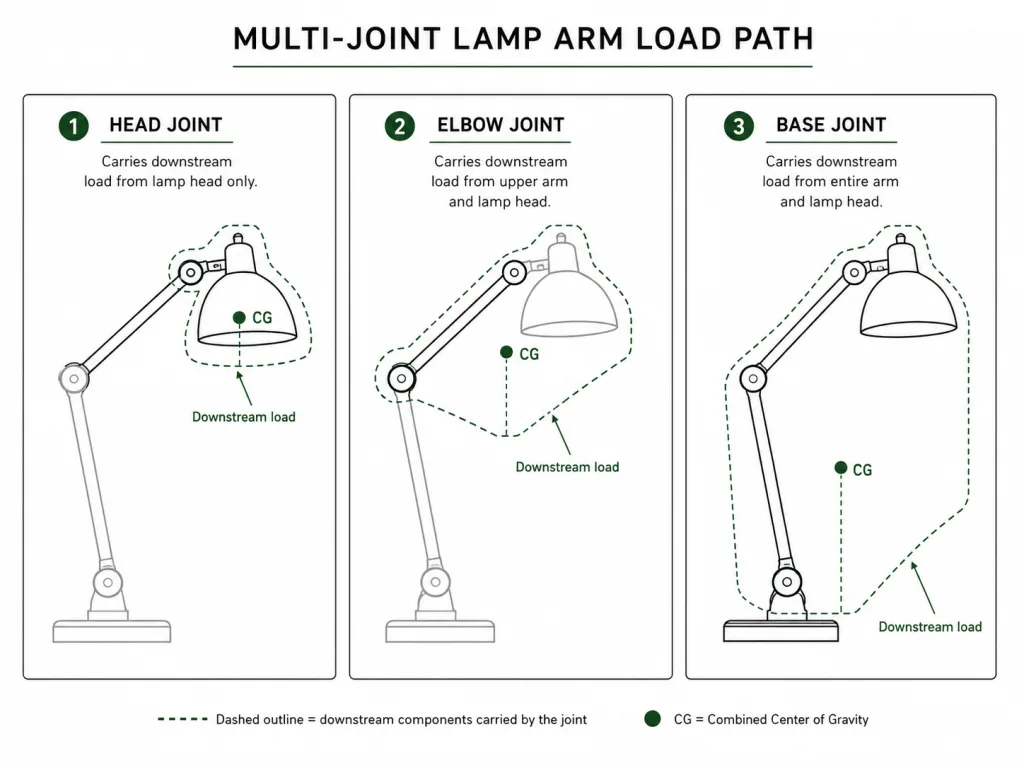
An articulated lamp should not be treated as one mass acting on three identical hinges. Each pivot carries the parts located downstream of that pivot.
The head joint may only need to resist the lamp head and the short hardware attached to it. The elbow joint may carry the head plus the upper arm section and wiring. The base joint can see the combined moment from nearly the entire moving assembly.
| Joint | Downstream Load to Include | Geometry That Matters | Engineering Action |
|---|---|---|---|
| Head pivot | Lamp head, shade, LED/heatsink package, local bracket and local cable | Head CG relative to the head-pivot axis | Calculate the worst-angle head moment and check the desired tilt range. |
| Elbow joint | Lamp head plus upper arm and everything mounted beyond the elbow | Combined downstream CG relative to the elbow | Use the assembled downstream mass distribution, not the head mass alone. |
| Base joint | All moving arm sections, head, brackets, cables and mounted accessories above the base pivot | Overall downstream CG and arm configuration | Compare required joint resistance with base stability during user adjustment. |
For a multi-part arm, the static gravity moment at one joint can also be estimated by summing the contribution of each downstream component: T ≈ Σ(mi × g × di), where di is the perpendicular distance from that joint axis to each component’s center of gravity in the evaluated pose.
This is usually clearer than trying to assign an arbitrary percentage of the total lamp weight to each hinge. The closer a joint is to the base, the more likely it is to be influenced by multiple downstream parts.
Holding Torque vs. Adjustment Effort
The hinge needs enough resistance to prevent drift at the demanding lamp position, but more torque is not automatically better.
The user must overcome the hinge resistance while repositioning the lamp. In a multi-joint arm, that effort can be transmitted through other joints and through the lamp base. A head joint that is far above the actual load requirement may feel secure when released yet make the lamp awkward to adjust with one hand.
This is also why a fixed “add 20%” or “add 30%” rule should not be applied blindly. The working margin depends on the hinge torque behavior, direction of motion, production tolerance, cable routing, expected wear, user-force target and whether the lamp has a stable base. Use the static calculation as the load starting point, then define the acceptable movement feel and holding behavior on the assembled product.
Static Hold, Breakaway and Running Torque
These are different behaviors and should not be treated as one number. Static holding torque describes whether the joint resists the lamp’s gravity moment after the user lets go. Breakaway torque is the resistance felt when motion first starts. Running torque is the resistance after the joint is already moving.
A joint can hold the lamp head correctly yet feel sticky at the start of motion if breakaway torque is much higher than running torque. The reverse problem is also possible: the joint may begin moving easily but provide too little resistance to hold a demanding angle. If a supplier publishes only one nominal torque value, confirm what that value represents and under what test condition before using it as the lamp’s acceptance target.
Tuning During Development
If the lamp head, cable package or arm geometry is still changing, an adjustable mechanism can be useful during prototype work because the resistance can be tuned within the product’s designed range. The broader trade-off between adjustable and fixed resistance is covered in the adjustable torque hinge guide. Once the lamp geometry is stable, the production decision should be based on the real torque window rather than on adjustability as a feature by itself.
When One Joint Moves Another
The lamp can hold position and still feel wrong. Consider a two-arm task lamp in which the elbow joint has enough resistance to hold the upper assembly, but the head joint is much lighter. The user pushes the lamp head to lower the entire arm. Instead of rotating mainly at the elbow, the head joint moves first and the light points downward. Increasing the elbow torque alone makes the user push harder and may begin to move the base. The design problem is not “insufficient torque” in one hinge. It is the relationship between the joint torques, user input point, downstream loads and structural stiffness. This is an illustrative engineering scenario, not a customer project record or product test claim.
Multi-joint coordination is easiest to judge by moving the lamp the way the user will. Push at the head, at the arm, and near the elbow. Watch which joint breaks away first and whether the other joints remain where they were intentionally set.
There is no universal rule that the base joint must be a fixed multiple of the head-joint torque. The correct relationship comes from the downstream moments, desired adjustment sequence and product feel. If the design needs one joint to stay fixed while another is adjusted, that behavior should be stated as an acceptance requirement and checked on the prototype.
The Hinge Holds, but the Head Still Drifts
Visible lamp-head movement does not prove the internal torque mechanism is slipping. The structure around the hinge can move while the hinge angle itself stays nearly unchanged.
| Observed Behavior | Likely Source | What to Inspect |
|---|---|---|
| Head slowly rotates around the hinge axis | Hinge torque below the actual gravity moment, or torque loss in the mechanism | Mark the hinge leaves and shaft reference, then check whether the relative hinge angle changes. |
| Lamp head moves but hinge reference marks stay aligned | Arm flex, bracket twist or plastic boss deformation | Inspect the mounting bracket, arm section and local fastener support under load. |
| Position changes after several adjustments | Fastener seating, bracket movement, joint wear or cable re-set | Check fastener movement and repeat the test with the cable fully routed. |
| Head returns slightly after the user lets go | Cable restoring torque, elastic arm deflection or interaction with another joint | Compare wired and temporarily de-coupled cable behavior where safe and practical. |
| Head has a small dead band or wobble but does not continuously sag | Joint free play, shaft clearance or mounting-interface clearance | Hold one side of the joint fixed and trace where the angular movement actually occurs. |
| Only one working angle drifts | Angle-dependent gravity moment, interference or local structural compliance | Measure the CG relationship and observe contact or flex at that angle. |
The distinction matters because replacing the hinge with a higher-torque part will not correct a bracket that twists under the same user load. It may make that bracket problem more severe.
Cable Routing Changes the Feel
A desk lamp is not a bare mechanical arm. LED power wires, USB leads, sensor cables or harness sleeves often pass through or around the same joints that provide position control.
As the joint rotates, a cable can bend, twist, slide through a guide or press against an arm wall. Those effects create angle-dependent resistance. In a low-torque head joint, even a modest cable restoring moment can be noticeable because it acts directly against the hinge’s holding behavior.
Route the production-intent cable before judging the final torque. Check both directions of travel. A harness that helps the hinge hold at one angle may pull the head back at another. Leave enough bend radius and service slack for the required motion, but do not create a loose loop that can snag or alter the visible lamp profile.
Prototype rule: a bare-arm torque test is useful for isolating the hinge, but it does not validate the finished lamp. The fully wired assembly is the product the user will adjust.
Define the Useful Rotation Range
More rotation is not automatically more useful. A table lamp needs the angles that place light where the product is designed to work without pulling the cable, colliding with the arm, exposing a pinch point or allowing the head to strike the base.
Define the working arc first. Then decide whether the joint needs a mechanical stop, a limited-angle hinge, continuous rotation, one-way resistance or resistance in both directions. The decision belongs to the lamp motion requirement, not to a marketing preference for the largest possible angle.
If a compact lamp design has already established that a limited one-way joint is appropriate, a model-specific page such as the 180-degree one-way torque hinge can be reviewed after the required torque, direction and envelope are known. That product page is for model fit; this article remains responsible for the lamp-level load logic.
Base Stability During Adjustment
A hinge can meet the holding requirement and still make the complete lamp unpleasant to use if the user has to apply enough force to slide or lift the base.
Base stability depends on more than base mass. The footprint, center of gravity of the complete lamp, desk-contact material, coefficient of friction, user push direction and current arm pose all affect whether the base stays planted while a joint is adjusted.
Watch for two different failures. Sliding occurs when the horizontal reaction at the desk exceeds the available friction. Tipping or base lift occurs when the applied moment shifts the resultant load toward or beyond the support footprint. A heavier hinge torque can increase both reactions because the user must push harder before the joint moves.
Do not solve base movement only by increasing base weight unless that is acceptable for the product. First check whether the joint torque is unnecessarily high, whether the user is expected to push at an unfavorable point, and whether the arm geometry creates a large adjustment moment.
What the Lamp Drawing Must Show
A supplier cannot select a meaningful lamp-arm torque from “lamp head weight” alone. The drawing or RFQ should make the moving geometry visible enough to evaluate each pivot.
- Mass of the lamp head and each downstream arm section
- Assembled center-of-gravity location, or enough geometry to establish it
- Pivot locations and axis directions
- Required working angles for each joint
- Desired holding direction: one-way or two-way resistance where relevant
- Mechanical-stop requirement and collision limits
- Cable route through or around each moving joint
- Available hinge envelope and mounting surfaces
- Whether the same lamp platform will use different head or arm options
If a required torque value has already been calculated, include the assumptions and the evaluated lamp pose rather than sending a number with no geometry. For commercial model browsing after those inputs are defined, use the rotational torque hinge range.
Validate the Fully Wired Lamp
The final sample should reproduce the mass, cable routing, mounting stiffness and base conditions of the production lamp closely enough to expose joint interaction.
- Worst-angle hold: place every joint in the pose that creates the highest expected gravity moment and check for drift after release.
- Adjustment effort: move the lamp from the intended user contact points and note whether the motion feels controlled without excessive force.
- Joint independence: adjust the head, elbow and base separately and observe whether an unintended joint moves first.
- Structural movement: watch brackets, arm sections, fasteners and plastic bosses rather than judging only the lamp-head angle.
- Cable effect: repeat the full range with the production-intent harness routed and secured.
- Hot-state behavior: if the joint sits near an LED heat sink, driver or another heat source, repeat the hold and adjustment checks after the lamp reaches a stabilized operating temperature. Do not assume room-temperature torque behavior represents the hot assembly unless the selected hinge data supports that assumption.
- Base behavior: check sliding, rocking and edge lift during one-hand adjustment.
- Repeated positioning: cycle the lamp through representative working angles and record any change in holding behavior or adjustment feel according to the project’s defined acceptance condition.
Any supplier torque or cycle-life value should remain tied to the exact hinge model and its stated test method. The complete lamp has additional loads and interfaces that a hinge-only bench test cannot reproduce.
Table Lamp Torque Hinge FAQ
How do I calculate torque for a table-lamp hinge?
Use the assembled downstream mass and the perpendicular center-of-gravity distance from the joint axis. For a simple horizontal pivot in a vertical motion plane, gravity moment can be estimated with T = m × g × L × sin(θ). Evaluate the most demanding working angle, then validate the complete lamp.
Is a higher-torque hinge better for a desk lamp?
Not automatically. Extra torque can reduce drift, but it also increases adjustment effort and can transfer more reaction into the arm, brackets and lamp base. The target is enough holding resistance with acceptable user effort.
Why does a lamp head drift even when the hinge feels tight?
The movement may come from arm flex, bracket twist, fastener movement or cable restoring torque rather than from the torque mechanism itself. Mark the hinge reference and inspect the complete structure while the lamp is loaded.
Should every joint in a multi-joint lamp use the same torque?
Usually not. Each pivot carries a different downstream mass and lever arm. The head, elbow and base joints should be evaluated separately, then tuned or selected so that one joint does not move unintentionally when another is adjusted.
Send the Lamp Arm Layout
Provide the lamp-head mass, arm-section masses, pivot locations, working angles, cable route and available hinge envelope. Those inputs make it possible to compare candidate torque ranges and joint forms without treating lamp-head weight as the only load.
Torque hinges for table lamps should be matched to the moment at each pivot, the usable adjustment effort and the behavior of the fully assembled lamp. Weight alone is not enough; center-of-gravity distance, arm geometry, cable routing and joint interaction decide whether the lamp actually holds position.