REQUEST A QUOTE

Adjustable One-Way Torque Hinges for Conveyor Covers: Load, Direction and Setup

When selecting one-way torque hinges for conveyor covers, cover weight alone is not the selection value. The hinge must resist the cover’s gravity moment at the angles where the cover must remain controlled. Move the center of gravity farther from the hinge axis and the required torque rises. Change the opening angle and the gravity moment changes again. That load geometry comes before model selection.

One-way resistance can be useful on inspection covers and access panels because the hinge can be oriented so that the resisted direction opposes gravity-driven closing while the opposite direction remains much lighter. The design goal is not “maximum torque.” It is low opening effort, enough closing-direction resistance, one clean hinge axis and a service angle that gives real maintenance access.

For a conveyor-cover application, the useful decision is whether the cover geometry and required motion fall inside the usable torque range of the selected hinge. General mechanism differences are covered in the adjustable torque hinge guide; the calculations below focus on cover load, hinge direction and installed motion.

The Cover Creates a Gravity Moment

Cover mass is only one input. The hinge reacts to the moment created around its axis. For a cover rotating in a vertical plane, a useful static starting point is:

Gravity moment about the hinge axis

Tg = m × g × L × sin(φ)

m = moving cover mass
g = 9.81 m/s²
L = hinge-axis-to-CG distance
φ = acute angle between the pivot-to-CG line and the vertical gravity line

m = 1.5 kgL = 0.15 mφ = 60°

Illustrative result: Tg ≈ 1.91 N·m

This is a mechanics example, not a recommended hinge setting or a customer-project value.

hinge axis CG W = m·g L φ

The useful point is simple: the same mass can require very different hinge torque when the center of gravity moves farther from the axis. A wide cover with light sheet metal can create more moment than a compact, heavier cover if its center of gravity sits much farther out.

Same 1.5 kg cover, CG at 150 mm

≈ 1.91 N·m

Using φ = 60° in this illustrative pose.

Same 1.5 kg cover, CG at 300 mm

≈ 3.82 N·m

Double the CG distance, and the gravity moment doubles.

Cover Angle Changes the Moment

The cover does not load the hinge equally through its opening range. In the formula above, the gravity moment is largest when the pivot-to-CG line is perpendicular to gravity. It becomes smaller as that line moves closer to vertical.

This is why “holds at 90°” and “holds anywhere” are not equivalent claims. A cover can be easy to hold near a near-vertical service position yet demand much more torque at a lower angle. The required service-open range therefore belongs on the drawing before the hinge is selected.

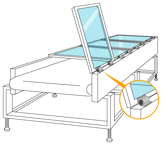
Conveyor cover opening angle and gravity moment around the hinge axis

Why One-Way Torque Hinges Fit Conveyor Covers

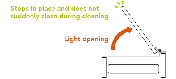
Opening and closing do not create the same user problem. When an operator lifts a cover, gravity already opposes the motion. Adding large friction in that same direction can make the cover unnecessarily hard to raise.

During closing, gravity helps the cover move downward. That is the direction in which controlled resistance can be useful. A one-way torque hinge can therefore be oriented so that the resisted direction works against gravity-driven closing while the reverse direction remains much lighter.

Direction must be verified on the real installation. “One-way” describes asymmetric torque behavior; it does not automatically mean “resists closing” in every mounting orientation. The hinge must be installed so its resisted direction matches the cover motion you intend to control.

Holding Torque Is Not Damping

A cover that remains open under a static load has passed one check. It has not automatically passed a closing-speed or impact check. Friction torque resists rotation; damping controls motion as a function of speed. Those are different behaviors.

If the cover is pushed downward, released from a low angle, hit by vibration or affected by an external force, its inertia becomes part of the motion. A one-way torque hinge may reduce the tendency to close, but the hinge should not be described as a soft-close device unless the exact model has documented damping behavior.

Static hold ≠ controlled closing speed. If the machine requirement is “the cover must not slam,” define an acceptance check for closing behavior on the real cover. If the requirement is “the cover must remain open against a specified disturbance,” define that disturbance separately from the gravity-moment calculation.

This distinction also keeps the product claim honest. An adjustable torque range can help match a static or quasi-static motion requirement; it does not by itself prove impact control, personnel protection or machine-safety performance.

Torque Window for the Cover Load

Once the cover gravity moment is known, compare it with the published adjustment range of the candidate hinge. HTAN’s current XG11-011 product page lists an adjustable torque range of 0 to 2.0 N·m for one hinge. That is a product range, not proof that a particular conveyor cover will work.

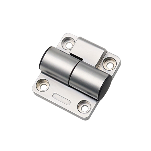
XG11-011 adjustable one-way torque hinge

The next question is what the published torque value actually represents: nominal resistance, a measured range under a defined test, opening-direction behavior, closing-direction behavior, or another supplier convention. If the product data does not state the test condition and tolerance, treat the range as a screening input and confirm the usable installed behavior with the supplier or sample.

For a first-pass calculation with two nominally identical hinges, engineers often divide the total required moment by two. That is useful only as an idealized starting point.

Illustrative two-hinge first pass

Tper hinge ≈ Tg ÷ n

Tg = 1.91 N·mn = 2 hinges

Idealized share ≈ 0.96 N·m per hinge

That value sits inside a 0–2.0 N·m published adjustment window, so the model may remain a candidate. It is not yet an approved selection.

Why the same model may stop being suitable

2.0 kg × 9.81 × 0.25 m ≈ 4.91 N·m

At φ = 90°, two hinges would have an idealized share of about 2.45 N·m each.

That exceeds a 2.0 N·m per-hinge window.

Illustrative mechanics only. Real selection still requires alignment, installed torque and validation.

This is the correct meaning of “one adjustable hinge can cover multiple cover configurations”: it can cover more than one configuration only when each configuration’s required torque remains inside the usable adjustment window and the installation still meets the operating-force and alignment requirements.

After the load is defined, the model-specific dimensions and current product data can be checked on the XG11-011 adjustable one-way torque hinge page.

Two Hinges, One Rotation Axis

Two hinges do not automatically share the cover moment equally. Equal sharing assumes both hinges are aligned, mounted on similarly stiff interfaces and adjusted to comparable torque behavior.

On a long sheet-metal cover, a small frame twist or hole-position error can make one hinge carry more frictional load than the other. The cover may still assemble. It may even close. Then the opening force rises sharply partway through travel because the two hinge axes are not truly collinear.

Local stiffness matters too. If one hinge is attached beside a reinforced corner while the other sits on a flexible flange, the mounting interfaces can rotate by different amounts under the same cover load. The nominal pin centerlines may be correct on the flat drawing, yet the loaded assembly no longer behaves like one rigid axis.

The Torque Is Correct, but the Cover Binds

Consider an illustrative cover whose gravity moment falls inside the selected hinge range. Two hinges are adjusted near the intended value, and the cover moves normally through the first part of travel. Beyond that point, opening effort climbs instead of staying smooth. The cause is not insufficient torque. A welded support flange has pulled one hinge axis slightly out of line with the other, so the structure begins to bind as the angle increases. Increasing hinge torque would make the symptom worse. The correction is axis alignment and mounting stiffness, not a stronger friction setting. This is an illustrative engineering scenario, not a customer project record or product test claim.

Conveyor cover with two torque hinges aligned on one rotation axis

Service Angle and Clearance

A cover should open as far as the maintenance task requires, not simply as far as the hinge can rotate. Define the real service angle from the operator’s access need and the machine envelope.

  • Hand, tool and cleaning access around the guarded area
  • Clearance to adjacent guards, frames, ducts or sensors
  • Cover edge movement through the full opening sweep
  • Any separate mechanical stop required by the machine design
  • Whether the hinge-line solution reduces external support hardware without creating a new interference

A compact torque hinge can reduce the external envelope used by stays or gas springs in some designs because the motion-control function is concentrated near the hinge line. That benefit is project-specific; it should not be converted into a universal claim that equipment height will always be reduced.

If the Hinge Is Exposed to Washdown

The XG11-011 product listing identifies a zinc-alloy body with a matte finish. That material description does not by itself establish washdown suitability, cleaning-chemical resistance, food-contact status or corrosion life in a conveyor installation.

If the cover sits near frequent washdown, moisture, product splash or aggressive cleaners, review the actual hinge location and exposure before final approval. A hinge outside the direct wash zone can face a very different environment from one mounted beside an exposed product path.

If washdown, food-zone exposure or aggressive cleaning chemicals are part of the project, review the material and environmental requirements separately in the food-processing equipment hinge guide.

Validate the Installed Cover

A hinge-only bench check cannot prove that the conveyor cover will behave correctly. The assembled cover adds real mass distribution, frame stiffness, axis tolerance, fastener movement and user input.

Installed CheckWhat It Tells YouWhat to Watch
Opening effortWhether the low-resistance direction is oriented correctly and acceptable to the userUnexpected force peaks, rubbing or a hinge installed in the wrong torque direction
Hold through service rangeWhether closing-direction resistance is sufficient at the required anglesSlow drop, sudden movement or a position that requires more torque than expected
Release / closing behaviorWhether the cover moves acceptably when the user lets go from representative positionsUnexpected acceleration, slam tendency or a motion that static holding alone did not reveal
Full-angle sweepWhether both hinges stay on one functional axisBinding that increases with angle
Cover stiffnessWhether the sheet-metal panel or mounting flanges distort under hinge reactionTwist near the hinge line or latch-side displacement
Adjustment retentionWhether the selected torque setting remains stable after representative operationChange in feel, loose adjustment hardware or asymmetric hinge behavior
Fasteners and bracketsWhether the load path stays fixed during repeated openingWitness marks, looseness or local bracket movement

Any cycle-life target, acceptable torque change, opening-force limit or hold criterion should come from the actual project or model-specific test evidence. Use model-specific or project-specific cycle evidence when setting acceptance limits for torque retention, opening force and repeated operation.

What to Send for Model Review

The fastest way to review a conveyor-cover hinge is to make the load geometry visible. A useful drawing or RFQ should include:

  • Cover mass, including handles, guards and hardware that move with it
  • Center-of-gravity location or enough geometry to establish it
  • Hinge-axis location and number of hinges
  • Required closed, intermediate and service-open angles
  • Preferred resisted direction and desired opening feel
  • Mounting-section thickness and available hinge envelope
  • Nearby obstructions through the cover sweep
  • Moisture, washdown or chemical exposure at the hinge location

Send the Conveyor Cover Layout

Send the cover mass, CG or dimensions, hinge-axis location, opening range, number of hinges and mounting section. Those inputs allow the required moment and the candidate torque window to be reviewed before a model is treated as suitable.

One-way torque hinges for conveyor covers should be selected from the cover moment, service angle and installed motion—not from cover weight or hinge torque range alone.

Conveyor Cover Torque Hinge FAQ

How do I calculate torque for a conveyor cover hinge?

Use the moving cover mass, hinge-axis-to-center-of-gravity distance and cover angle. For a simple cover rotating in a vertical plane, the gravity moment can be estimated with T = m × g × L × sin(φ). The result is a load calculation, not a final hinge setting.

Can two torque hinges simply share the conveyor cover load equally?

Only as an idealized first estimate. Real load sharing depends on hinge-axis alignment, mounting stiffness, torque adjustment and manufacturing tolerance. One hinge may carry more load if the two mounting interfaces do not behave the same way.

Why use a one-way torque hinge on a conveyor cover?

A one-way torque hinge can be oriented so that the resisted direction opposes gravity-driven closing while the opening direction remains much lighter. The actual resisted direction must be confirmed for the selected hinge and installation orientation.

Does a torque hinge prevent a conveyor cover from slamming shut?

Not automatically. Static holding torque and damping are different behaviors. A torque hinge may resist closing, but closing speed, inertia and impact behavior must still be checked on the complete cover assembly.

Anson Li
Anson Li

Hi everyone, I’m Anson Li. I’ve been working in the industrial hinge industry for 10 years! Along the way, I’ve had the chance to work with more than 2,000 customers from 55 countries, designing and producing hinges for all kinds of equipment doors. We’ve grown together with our clients, learned a lot, and gained valuable experience. Today, I’d love to share some professional tips and knowledge about industrial hinges with you.

Articles: 560

Newsletter Updates

Enter your email address below and subscribe to our newsletter