HTAN ist einer der führenden Hersteller von industriellen Scharnieren, Griffen und Verschlüssen in China.


Eine Maschinentür kann sich zwar reibungslos öffnen, am Ende ihres Hubs jedoch dennoch fehlerhaft konstruiert sein. Ohne einen festgelegten mechanischen Anschlag kann sich die Tür so lange drehen, bis ein Scharnierblatt den Rahmen berührt, ein Seil straff wird, ein Erdungsband die Rückhaltekraft aufnimmt oder ein Griff gegen die nächste Maschinenverkleidung stößt.
Richtig Anschläge für die Maschinentüröffnung Es muss ein kontrollierter Maximalwinkel festgelegt werden, bevor eine dieser Bedingungen eintritt. Der Anschlag muss außerdem die endgültige Öffnungslast auf die verstärkte Tür- und Rahmenkonstruktion übertragen, anstatt sie auf einen Scharnierstift, eine dünne Blechhaut, einen Verriegelungsantrieb, ein Verbindungsstück oder eine bewegliche Versorgungsleitung zu konzentrieren.
In dieser Anleitung wird erläutert, wie man den erforderlichen Schwenkwinkel festlegt, den ersten unsicheren Zustand ermittelt, den gesamten Schwenkbereich abbildet, eine Anschlagarchitektur auswählt, einen statischen Lastpfad aufbaut, bewegliche Leitungen und angrenzende Paneele schützt und das fertige Öffnungs- und Anschlagsystem validiert.
Entwurfsgrenzen
Dieser Artikel befasst sich mit seitlich angeschlagenen Maschinenschutztüren, Gehäusetüren und Wartungstüren. Ein konstruktiver Öffnungsanschlag begrenzt den maximalen Schwenkbereich. Er hält die Tür nicht automatisch offen, verringert nicht die Öffnungsgeschwindigkeit und stützt keine sich nach oben öffnende Abdeckung.
Abdeckungen mit Öffnung nach oben, bei denen eine Positionsarretierung erforderlich ist, sollten gesondert geprüft werden. Die Führungsschiene für Deckelhalterung mit freier Arretierung im Vergleich zu einer mit festem Winkel erläutert, ob eine Geräteabdeckung an beliebigen Stellen oder nur an festgelegten Positionen angebracht werden soll.
Legen Sie den erforderlichen Betriebswinkel und den maximalen Sicherheitswinkel fest
Wählen Sie nicht gleich zu Beginn einen Anschlag aus einem Katalog aus. Beginnen Sie mit der Wartungs- oder Betriebsaufgabe, für die die offene Tür geeignet sein muss.
Ein Techniker muss möglicherweise eine Komponente überprüfen, einen Filter entfernen, einen Motor ausbauen, Prüfgeräte anschließen, auf einen Klemmenblock zugreifen oder ein Modul durch die Öffnung austauschen. Für jede dieser Aufgaben kann ein anderer minimaler Öffnungswinkel der Tür erforderlich sein.
| Erforderliche Eingabe | Projektquelle | Warum es notwendig ist |
|---|---|---|
| Mindestbetätigungswinkel | Wartungsablauf, Wartungsanalyse oder Vorgehensweise zum Ausbau von Bauteilen | Die Tür muss sich weit genug öffnen lassen, um die vorgesehenen Arbeiten ausführen zu können |
| Erster unsicherer Winkel | Überprüfung der Maschinenanordnung und des Hubvolumens | Ermittelt die früheste Kollision, den frühesten Überhub, die früheste Einklemmung oder die früheste Betriebsgrenzwertüberschreitung |
| Toleranz des tatsächlichen Winkels | Toleranzen für Tür, Rahmen, Scharnier, Anschlag, Unterlegscheibe, Beschichtung und Montage | Der tatsächliche Stoppwinkel wird nicht genau einem perfekten Nennwert entsprechen. |
| Überschwingen verhindern | Stoßfängerkompression, Durchbiegung der Halterung, Dehnung des Haltegurts oder strukturelle Nachgiebigkeit | Die Tür kann sich nach dem ersten Berühren des Anschlags weiterbewegen |
| Öffnungsgeschwindigkeit | Betreiberstudie, Stellantriebsprofil oder projektspezifische Betriebsbedingungen | Eine höhere Geschwindigkeit erhöht die kinetische Energie beim Anhalten |
| An der Tür angebrachte Vorsprünge | Vollständige Stückliste und CAD-Modell der Tür | Griffe, Verriegelungen, Fenster, Bedienoberflächen und Halterungen können den tatsächlichen Schwenkradius bestimmen |
| Umzugsservice | Elektrische, pneumatische, hydraulische und Erdungskonzeption | Der Anschlag muss greifen, bevor ein Kabel, ein Schlauch oder ein Verbindungsband seine Endposition erreicht |
| Angeschlossene Geräte | Anordnung der Maschinenzellen und des Aufstellungsortes | Eine freistehende, durchsichtige Tür könnte gegen eine andere installierte Maschine stoßen |
| Vorgabe zur Offenhaltung | Betriebs- und Wartungsanleitung | Nach Erreichen des Anschlags ist möglicherweise eine separate Halterung, Stütze, Arretierung oder Haltevorrichtung erforderlich |
Die Begrenzung des Öffnungswinkels sollte den gesamten Toleranz- und Auslenkungsbereich berücksichtigen:
θservice,max ≤ θstop,min
θstop,max + θÜberhub < θunsicher, min
Der tatsächliche Mindestanschlagwinkel muss weiterhin den erforderlichen Wartungszugang gewährleisten. Der tatsächliche maximale Anschlagwinkel – einschließlich Toleranz, Stoßfängerkompression, Seilausdehnung, Halterungsdurchbiegung und sonstigem projektspezifischem Überhub – muss unterhalb des frühesten unsicheren Zustands bleiben.
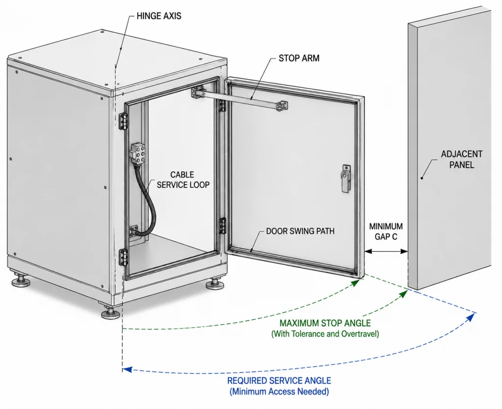
Es gibt keinen allgemein gültigen, korrekten Öffnungswinkel für jede Maschinentür. Eine kompakte Filterzugangstür und eine breite Schutzabdeckung für eine Roboterzelle erfordern möglicherweise unterschiedliche Grenzwerte, selbst wenn sie mit ähnlichen Scharnieren ausgestattet sind.
Den gesamten Schwenkbereich der Tür abbilden
Die sichtbare Türkante ist nicht immer das Merkmal, das den Freiraum bestimmt. Der am weitesten hervorstehende Punkt kann ein Türgriff, ein Schließblechgehäuse, ein Verriegelungsbetätiger, ein Sichtfensterrahmen, eine Seilführung, eine Türverstärkung oder ein an der Innenseite montiertes Bauteil sein.
Erstellen Sie den Schwenkbereich von der funktionalen Scharnierachse zu jedem wesentlichen beweglichen Bauteil. Überprüfen Sie den gesamten Bewegungsweg von der geschlossenen bis zur vollständig angehaltenen Position, anstatt nur die Endposition zu kontrollieren.
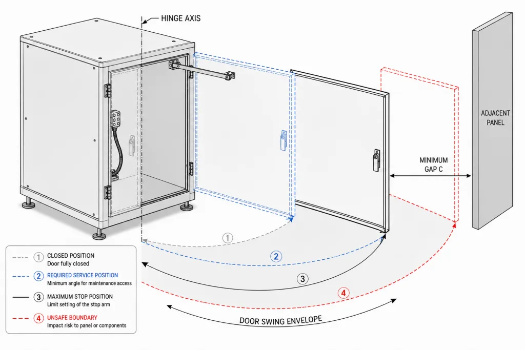
- Bestimmen Sie die funktionelle Scharnierachse. Orientieren Sie sich an der Mittellinie des Stifts oder des Zylinders und nicht an der Außenkante des Scharnierflügels.
- Geben Sie die gesamte Türstärke an. Innenrahmen, Dämmung, Schutzvorrichtungen und hervorstehende Beschläge können hinter die nominelle Plattenebene ragen.
- Beziehen Sie das am weitesten entfernte äußere Merkmal mit ein. Überprüfen Sie Türgriffe, Schließbleche, Schlösser, Fenster, Blinker und Halterungen.
- Beziehen Sie interne Umzugsdienste mit ein. Eine Versorgungsschleife, ein Schlauch, ein Erdungsband oder eine Kabelführung kann sich während der Bewegung über das starre Türprofil hinaus erstrecken.
- Zwischenwinkel prüfen. Ein Bauteil kann zwar in der geschlossenen und der letzten offenen Position freiliegen, berührt jedoch in der Mitte des Schwenkwegs den Rahmen oder ein anderes Teil.
- Überprüfen Sie, ob sich die Türen gleichzeitig bewegen. Doppeltüren und benachbarte Revisionsklappen können denselben Raum einnehmen, wenn beide geöffnet sind.
- Überprüfen Sie die installierte Maschinenzelle. Dazu gehören Wände, Säulen, Förderbänder, Kabelrinnen, Poller, Schutzvorrichtungen, benachbarte Maschinen, Gänge und Arbeitsbereiche des Bedieners.
Der Freiraum muss unter Berücksichtigung der Projektgeometrie, der Fertigungstoleranzen, der Montageabweichungen, der zu erwartenden Rahmenbewegungen und der Wartungsarbeiten festgelegt werden. Ein nominelles CAD-Modell allein gibt möglicherweise nicht den Mindestfreiraum vor Ort wieder.
Trennung der Funktionen „Stopp“, „Offenhalten“ und „Dämpfung“
Mehrere Geräte können dieselbe Türbewegung beeinflussen, erfüllen jedoch nicht dieselbe technische Funktion.
| Funktion | Hauptberuf | Gehen Sie nicht davon aus, dass es so sein wird |
|---|---|---|
| Anfangshaltestelle | Verhindern, dass die Drehung einen festgelegten Maximalwinkel überschreitet | Die Tür trotz Schwerkraft, Wind, Vibrationen oder Eingriffen durch den Bediener offenhalten |
| Feststellvorrichtung | Die Tür in der gewünschten Wartungsposition arretieren | Unkontrollierte Stöße abfedern, sofern keine zugelassene Aufprallfestigkeit vorliegt |
| Dämpfer | Die Winkelgeschwindigkeit verringern oder den Endanflug abmildern | Bereitstellung einer endgültigen strukturellen Hubbegrenzung ohne separaten Nennanschlag |
Eine Tür kann alle drei Funktionen erfordern. Ein Dämpfer kann die Annäherungsgeschwindigkeit verringern, ein verstärkter Anschlag kann den maximalen Hub begrenzen und eine separate Haltevorrichtung kann die geöffnete Tür gegen Luftströmung, Wind, Maschinenvibrationen oder eine schräge Einbaulage sichern.
Ein Drehmomentscharnier oder ein Reibungsscharnier kann zwar einer Bewegung Widerstand leisten und die Position halten, sollte jedoch nicht als Stoßanschlag betrachtet werden, es sei denn, der Lieferant bestätigt den zulässigen Anschlagwinkel, das statische Moment, die Stoßbedingungen, das Trägheitsmoment, die Öffnungsgeschwindigkeit, die Zyklusbelastung, die Temperatur und die Einbaulage.
Wählen Sie eine Anschlagkonstruktion, die zum Türverhalten passt
Die geeignete Anschlagkonstruktion hängt von der erforderlichen Winkelwiederholgenauigkeit, dem verfügbaren Platz, der Öffnungsgeschwindigkeit, den Umgebungsbedingungen, dem Wartungszugang sowie der Steifigkeit von Tür und Rahmen ab.
| Stop-Architektur | Nützliche Eigenschaften | Größtes technisches Risiko |
|---|---|---|
| Am Rahmen befestigter fester Anschlag | Wiederholbarer Endwinkel und potenziell direkter Lastpfad in der Konstruktion | Hohe Spitzenbelastung, wenn eine sich bewegende Tür auf einen starren Kontakt trifft |
| Fester Anschlag mit austauschbarem Anschlagpuffer | Definierter Winkel bei geringer Geräuschentwicklung und minimalen lokalen Oberflächenbeschädigungen | Ein weicher Stoßfänger gleicht eine schwache Halterung oder eine nicht abgestützte Türverkleidung nicht aus |
| Nenn-Begrenzungsarm | Führungsvorrichtungen für Fälle, in denen kein direkter Kontakt zwischen Tür und Rahmen möglich ist | Verformung der Arme, Gelenkverschleiß, Quetschstellen, seitliche Belastung und Versagen der Befestigung |
| Zugelassene Rückhalteleine oder -kette | Kompakter Hubbereich, bei dem ein fester Kontakt nicht praktikabel ist | Stoßbelastung, Versagen der Befestigung, Schwankungen der Durchhanglänge, Verhaken, Abrieb und ungenauer Endwinkel |
| Dämpfer plus struktureller Anschlag | Verringert die Anfluggeschwindigkeit vor einer festgelegten baulichen Begrenzung | Die Dämpferleistung kann sich in Abhängigkeit von Temperatur, Geschwindigkeit, Verschleiß und Ausrichtung ändern |
| Scharnier mit integriertem Anschlag | Kompakte, integrierte Lösung für den Einsatz bei begrenztem Einbauraum | Die interne Stoppkraft kann geringer sein als die tatsächliche Stoß-, Wind- oder Antriebslast |
Eine Sicherungsleine oder -kette sollte nur verwendet werden, wenn ihre Nennlast, ihre Befestigungspunkte, ihr Durchhang, ihre Stoßbelastung, ihre Abriebbelastung, die Umgebungsbedingungen und die Zyklenzahl für die jeweilige Türbaugruppe überprüft wurden.
Bei großen Maschinenschutzvorrichtungen, Außentüren, breiten flexiblen Paneelen oder motorbetriebenen Türen sind ein kontrollierter konstruktiver Anschlag und eine projektspezifische dynamische Überprüfung in der Regel besser geeignet als eine nicht geprüfte flexible Rückhaltevorrichtung.
Den Anschlag anbringen und die Last auf die verstärkte Konstruktion übertragen
Der Öffnungsanschlag dient nicht nur der Winkeleinstellung. Er ist ein Lastübertragungssystem, das am Kontaktpunkt der Tür beginnt und in der Hauptkonstruktion der Maschine endet.
Wählen Sie eine Region für „Stable Door“ aus
- Verwenden Sie verstärkte Kontaktflächen. Richten Sie den Anschlag an einem inneren Türrahmen, einer geformten Umbiegung, einer geschweißten Verstärkung, einem Konstruktionsrohr oder einer dafür vorgesehenen Befestigungsplatte aus.
- Vermeiden Sie nicht unterstützte Sheet-Skins. Wiederholter Kontakt kann zu Dellen, Beschädigungen der Beschichtung, bleibenden Verformungen und einer Veränderung des Anstellwinkels führen.
- Bevorzugen Sie einen breiten, stabilen Kontakt. Ein Kontakt an Kanten oder Ecken kann zu einem Verrutschen führen, die Beschichtung beschädigen oder eine ungleichmäßige Endposition zur Folge haben.
- Steuern Sie die Anflugrichtung. Die Stirnflächen sollten aneinanderstoßen, ohne dass dabei eine übermäßige seitliche Belastung auftritt, die einen Begrenzungsarm verbiegt oder eine Halterung aus der Ebene drückt.
- Austauschbare Verschleißteile aufbewahren. Ein Stoßfänger oder eine Verschleißplatte darf sich während des Radfahrens nicht verschieben, aufspalten, verdrehen oder herausfallen.
- Berücksichtigen Sie die Toleranz. Unterschiede bei Tür, Rahmen, Scharnier, Beschichtung, Unterlegscheibe und Montage dürfen keinen Einfluss darauf haben, welches Bauteil zuerst Kontakt hat.
- Prüfen Sie breite oder flexible Türen. Eine einzelne lokale Befestigung kann eine große Platte verziehen; unter Umständen sind zwei aufeinander abgestimmte Befestigungspunkte oder eine zusätzliche Verstärkung erforderlich.
Den statischen Lastpfad aufbauen
Türkontaktplatte → Türverstärkung → Anschlagfläche oder Begrenzungsarm → verstärkte Halterung → Hauptrahmen der Maschine
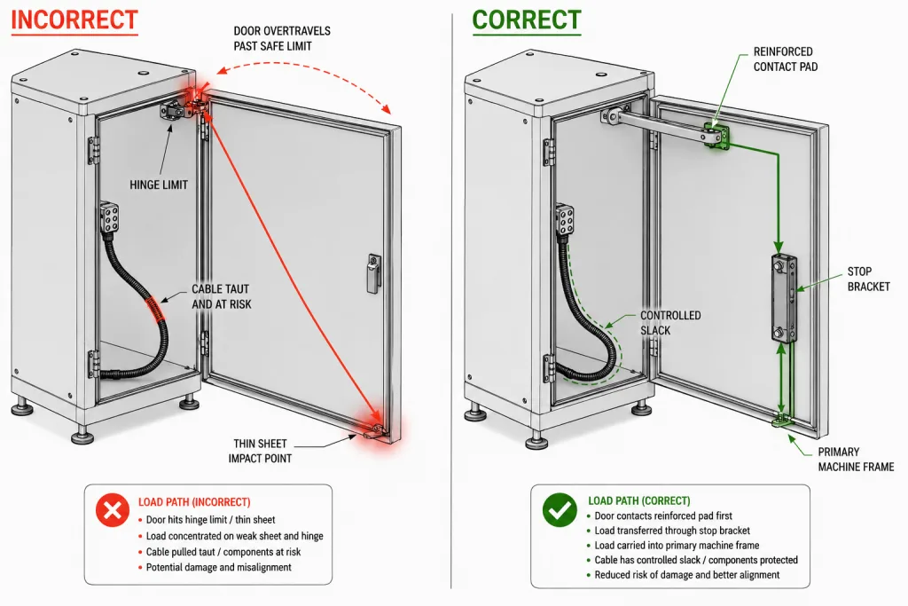
Ein Anschlag, der auf die Mitte einer nicht abgestützten Tür trifft, kann die Tür verbeulen, selbst wenn die Anschlaghalterung und das Scharnier unbeschädigt bleiben. Eine kleine Halterung, die an einem flexiblen Flansch befestigt ist, kann sich verdrehen, ihre Bohrungen ausdehnen, ihre Schweißnaht reißen lassen oder den Öffnungswinkel allmählich verändern.
Sowohl die Stütze unter dem Türkontakt als auch die Stütze unter der rahmenseitigen Halterung müssen überprüft werden. Eine bloße Vergrößerung des Durchmessers des Anschlagstifts behebt weder ein nachgiebiges Türrücklaufverhalten noch eine schwache Rahmenwand.
Überprüfung der statischen Stoppanforderung
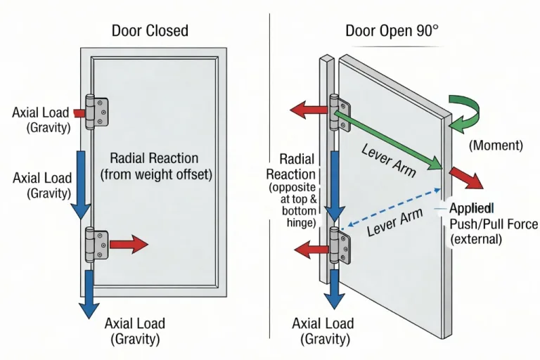
Bei einer Tür, die sich auf einer waagerecht aufgestellten Maschine um eine im Wesentlichen vertikale Scharnierachse dreht, wirken sich das Türgewicht und der Schwerpunkt in erster Linie auf die Belastungen der Scharnierlager und das Drehträgheitsmoment aus. Sie erzeugen für sich genommen kein statisches Öffnungsmoment um die vertikale Achse.
Die statische Haltekraft kann stattdessen durch Wind, eine geneigte Schwenkachse oder ein Maschinenfundament, eine Feder oder eine Drehmomentvorrichtung, einen Aktuator, eine vom Bediener ausgeübte Kraft oder eine andere äußere Belastung entstehen.
MNachfrage = Σ(Fi × ri)
Für einen dominanten Anschlagkontakt unter quasi-statischen Bedingungen:
FStopp ≈ MNachfrage ÷ rStopp
Hierbei handelt es sich um allgemeine mechanische Zusammenhänge. Sie stellen weder eine universelle Stoppbewertung, einen Sicherheitsfaktor, einen Aufprallmultiplikator noch eine Produktionsabnahmegrenze dar.
Wird ein Anschlag weiter von der Scharnierachse entfernt angebracht, kann dies die Kontaktkraft verringern, die erforderlich ist, um dem gleichen Drehmoment standzuhalten. Diese Stelle muss jedoch weiterhin mit einem ausreichend steifen und verstärkten Bereich der Tür und des Rahmens übereinstimmen.
Verwenden Sie die Leitfaden zur Tragfähigkeit von Industrie-Scharnieren um das Scharnier und die Befestigungskonstruktion unter dem gesamten Türgewicht zu überprüfen. Diese Berechnung allein bestimmt noch nicht die Öffnungsanschlagbelastung.
Überprüfung der dynamischen Stoppenergie
Wenn eine sich bewegende Tür den Anschlag erreicht, umfasst der entsprechende Zustand die Rotationskinetikenergie:
Ek = ½Iω²
Wo I ist das Trägheitsmoment der gesamten Türbaugruppe um die Scharnierachse und ω ist seine Winkelgeschwindigkeit unmittelbar vor dem Berühren des Anschlags.
Die Energie allein bestimmt nicht die maximale Kontaktkraft. Bremsweg, Stoßfängerverformung, Dehnung des Verbindungsseils, Steifigkeit von Halterung und Rahmen, Kontaktgeometrie, Dämpfung, Rückprall und lokale Verformung beeinflussen das Ergebnis.
Wenden Sie keinen nicht dokumentierten universellen Aufprallmultiplikator an. Bei Außentüren ist unter Umständen auch eine Windprüfung in geöffneter Position erforderlich, während bei motorbetriebenen Türen die Bedingungen hinsichtlich Antrieb, Bremsung, Steuerungsfehler und möglicher Hindernisse separat bewertet werden müssen.
Die Norm ASME Y14.5-2018 (R2024) kann zur Festlegung von Bezugspunkten, Winkelmaßen, Anschlagpositionen und den damit verbundenen geometrischen Toleranzen in der freigegebenen Zeichnung herangezogen werden. Sie legt weder den sicheren Öffnungswinkel, die zulässige Anschlaglast, die Seilbegrenzung, die Aufprallbedingungen noch projektspezifische Abnahmekriterien fest.
Stellen Sie den Stopp so ein, dass Kabel, Schläuche oder Erdungsbänder ihre Grenzen nicht erreichen
Ein sich bewegendes Kabel, ein Schlauch, eine Kabelführung oder ein Erdungsband darf nicht zu dem Bauteil werden, das die Tür zum Stillstand bringt. Überlastung der Steckverbinder, Beschädigungen der Leiter, sich lösende Klemmen, Knicke im Schlauch und Verschleiß der Isolierung können bereits auftreten, bevor ein äußerer Defekt sichtbar wird.
| Prüfung der Start- und Stopp-Positionen | Notwendige Bedingung | Ausfallrisiko |
|---|---|---|
| Erster Kontakt | Die vorgesehenen strukturellen Anschlagkontakte, bevor der bewegliche Teil seine mechanische Endlage erreicht | Das Kabel, der Schlauch, der Gurt oder die Halterung wird zu einer unbeabsichtigten Fessel |
| Verbleibender Bewegungsspielraum | Die kontrollierte Durchhängung und die projektspezifische Biegebedingung bleiben auf dem maximalen tatsächlichen Anschlagwinkel | Spannung an den Steckverbindungen, Schlauchverengungen, Materialermüdung oder Verhakungen |
| Klemmspiel | Kein Kontakt mit dem Flügel, dem Rahmen, dem Anschlag, der Verriegelung, der Schließkante oder angrenzenden Einrichtungen | Durchtrennte Isolierung, gequetschter Schlauch, sporadische Störungen oder Abrieb |
| Ankersicherheit | Stationäre und bewegliche Verankerungen verschieben die Haltekraft nicht und leiten sie auch nicht auf Verbindungselemente und Anschlüsse weiter | Lose Anschlüsse, beschädigte Zugentlastung oder sich ändernder Türwiderstand |
In diesem Abschnitt wird die mechanische Verbindung zwischen dem Öffnungsanschlag und den beweglichen Komponenten geprüft. Die detaillierte Kabelauswahl, die Berechnung des Biegeradius, die Dimensionierung der Leiter, die Abschirmung, die Anordnung der Steckverbinder, die Auslegung der Zugentlastung, die Durchgängigkeit der Potentialausgleichsverbindungen sowie die langfristige Biegelebensdauer sind in einer separaten Spezifikation zur Kabelführung bei Klapptüren zu regeln.
Schützen Sie benachbarte Paneele, Geräte und Wartungsgänge
Eine Maschinentür kann im Modell des Einzelgeräts zwar ausreichend Platz bieten, nach der Installation jedoch dennoch zu Kollisionen führen. In der Nähe befindliche Maschinen, Kabelrinnen, Schutzeinrichtungen, Säulen, Poller, Wände, Förderbänder, Treppen und temporäre Wartungsausrüstung können den verfügbaren Schwenkraum einschränken.
- Wird der Griff, das Schloss oder die HMI-Einheit vor der Türkante gegen die nächste Verkleidung stoßen?
- Können zwei benachbarte Türen gleichzeitig geöffnet werden?
- Versperrt die geöffnete Tür einen Gang, einen Kontrollposten, einen Fluchtweg oder ein abnehmbares Maschinenmodul?
- Passt das benötigte Werkzeug oder das Ersatzteil durch die verbleibende Öffnung?
- Führen Maschinenausrichtung, Verankerung oder Rahmenverdrehung zu einer Verringerung des Nennabstands?
- Können Wind, Luftströmungen, Bodenneigungen oder Vibrationen dazu führen, dass sich die Tür aus ihrer vorgesehenen Betriebsposition verschiebt?
- Entsteht durch die offene Tür ein Bereich zwischen den Maschinenteilen, in dem etwas eingeklemmt werden kann?
Wenn eine Maschinenplattform in mehreren Aufstellungsvarianten installiert wird, legen Sie den Anschlag anhand des zulässigen Aufstellungsrahmens fest oder geben Sie standortspezifische Anschlagkonfigurationen frei. Ein maximaler Winkel ist möglicherweise nicht bei jeder Aufstellung zulässig.
Verwenden Sie das Scharnier, die Verriegelung oder den Transportdienst nicht als nicht ausgewiesene Haltestelle
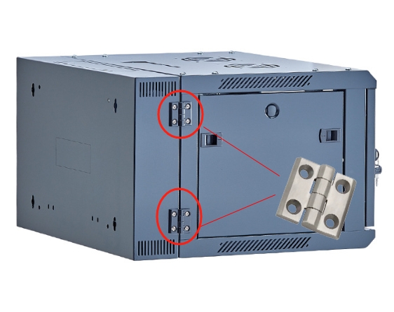
Ein Scharnier hat das Ende seiner geometrischen Drehbewegung erreicht, wenn ein Flügel, ein Scharnierkörper, ein Bolzen, ein Rahmen oder ein internes Scharnierteil Kontakt aufnimmt. Dies bedeutet jedoch nicht automatisch, dass das Scharnier die daraus resultierende statische Belastung, Stoßbelastung, Windlast oder Belastung durch eine motorbetriebene Tür aufnehmen kann.
Bestätigung durch den Lieferanten erforderlich: Bevor ein internes Scharnier als Öffnungsanschlag betrachtet wird, sind das Scharniermodell, der Anschlagwinkel, das zulässige statische Moment, die Stoßbedingungen, das Trägheitsmoment, die Öffnungsgeschwindigkeit, die Zyklusanforderungen, die Temperatur, die Einbaulage und die Abnahmekriterien zu überprüfen.
Die folgenden Komponenten sollten nicht versehentlich als Öffnungsanschläge dienen:
- Kontakt zwischen Scharnierflügel und Scharnierzylinder, der nicht durch eine dokumentierte Anschlagkraftangabe abgedeckt ist
- Haltevorrichtung für Scharnierstifte
- Betätiger oder Schaltergehäuse für eine Sicherheitsverriegelung
- Verriegelungsgestänge oder Schließblech
- Elektrisches Kabel, Schlauch, Kabelführung, Stecker oder Erdungsband
- Türgriff, der eine angrenzende Verkleidung berührt
- Fensterrahmen, Dichtung, Typenschild oder Kante einer Zierblende
Die in diesem Artikel beschriebene Überprüfung der Verriegelung bezieht sich ausschließlich auf den mechanischen Abstand und den Kontakt. Sie dient nicht zur Validierung des Sicherheitskreises, der Schutzverriegelungsfunktion, des Diagnosebereichs oder der erforderlichen funktionalen Sicherheitsleistung.
Überprüfung der Anschläge für die Maschinentüröffnung an der kompletten Baugruppe
Der Anschlag muss an einer serienreifen oder repräsentativen Türbaugruppe überprüft werden. Ein Anschlag, der bei einer leichten, unbearbeiteten Türfüllung funktioniert, kann sich nach dem Einbau von Fenster, Türgriff, Verriegelung, HMI, Verkabelung, Dämmung, Schutzvorrichtung und innerer Verstärkung anders verhalten.
- Vervollständigen Sie das Öffnungssystem. Montage der entsprechenden Tür, der Scharnierbefestigung, des Anschlags, des Stoßfängers oder der Haltevorrichtung, der Türbeschläge, der Transportdienstleistungen sowie der angrenzenden Konstruktion.
- Führen Sie eine langsame, kontrollierte Schwenkbewegung durch. Vergewissern Sie sich, dass der vorgesehene Anschlag das erste Bauteil ist, das den Kontakt herstellt und eine Weiterbewegung verhindert.
- Messen Sie den tatsächlichen Stoppwinkel. Erfassen Sie den Winkel anhand der definierten Bezugspunkte des Maschinenrahmens und der Tür, nicht nur anhand eines Katalogwerts.
- Überprüfen Sie den gesamten Schwungbereich. Überprüfen Sie den Zugang zur Anlage, die Kabelführung, den Klemmabstand und den Abstand zu benachbarten Bauwerken bei Zwischen- und Endwinkeln.
- Wenden Sie die projektspezifische Öffnungsbedingung an. Geben Sie repräsentative Werte für manuelle Geschwindigkeit, motorisierte Bewegung, Wind, Luftströmung, Neigung oder andere relevante Bedingungen an.
- Wiederholen Sie die erforderliche Betriebsbelastung. Überprüfen Sie nach den festgelegten Zyklen oder Ereignissen erneut den Winkel, die Kontaktfolge, die Halterungsposition, die Verstärkung, die Verschleißteile, die beweglichen Teile und den Abstand zu benachbarten Bauteilen.
| Nachweis für einen bestimmten Haltepunkt | Was soll aufgezeichnet werden? |
|---|---|
| Tatsächlicher Stoppwinkel | Ausgangswinkel, Bezugspunktmethode, Toleranz und Winkel nach der Prüfung |
| Ablauf des Erstkontakts | Welche Oberflächen berühren sich zuerst beim Öffnen mit langsamer und mit typischer Geschwindigkeit? |
| Stopp-Last-Zustand | Trägheit der Tür, Öffnungsgeschwindigkeit, äußere Kraft, Wind, Stellantrieb, Neigung und gegebenenfalls Prüflage |
| Umzugsgenehmigung | Verbleibendes Spiel, Klemmspiel, Abrieb und Verankerungsstabilität |
| Abstand zu benachbarten Bauteilen | Mindestabstand zu Schalttafeln, Griffen, Wänden, Geräten und Wartungswegen |
| Bauzustand | Kontaktplatte, Stoßfänger, Begrenzungsarm oder Haltegurt, Halterung, Befestigungselemente oder Schweißnähte, Verstärkung und Hauptrahmen |
Nachdem der Anschlagwinkel und der strukturelle Lastpfad definiert wurden, verwenden Sie die Validierung der Türscharnierbaugruppe einer Maschine Leitfaden zur Überprüfung der vollständig beladenen Tür, der Ausgangsgeometrie, der Betriebsbelastung und der Wiederholbarkeit nach dem Test vor der Freigabe für die Produktion.
Die Art der Scharnierbefestigung sollte ebenfalls vor der abschließenden Validierung geklärt werden. Verwenden Sie die Anschweißbare versus anschraubbare Scharnierführung wobei die Montagearchitektur offen bleibt.
Symptome eines Fehlers beim Öffnen und Schließen richtig deuten
| Beobachtetes Symptom | Zuerst die Rezension | Gehen Sie nicht davon aus, dass |
|---|---|---|
| Das Scharnierblatt verbiegt sich, wenn die Tür zu stark geöffnet wird | Fehlende Halteposition, Erstkontaktsequenz, Öffnungsgeschwindigkeit und struktureller Lastpfad | Schon ein größeres Scharnier allein löst das Problem des unkontrollierten Überhubs |
| Das Kabel oder der Erdungsbügel spannt sich, bevor der Anschlagkontakt erreicht wird | Stoppwinkel, Route, verbleibender Bewegungsspielraum und Ankerpositionen | Die Transportvorrichtung kann problemlos als sekundäre Rückhaltevorrichtung dienen |
| Die Halterung verändert ihren Winkel allmählich | Steifigkeit der Halterung, Rahmenabstützung, Befestigungselemente oder Schweißnähte sowie dynamischer Zustand | Der ursprüngliche Winkel wurde einfach falsch gemessen |
| Die Tür prallt kräftig vom Anschlag zurück | Öffnungsgeschwindigkeit, Trägheit, Stoßfängersteifigkeit, Bremsweg und Dämpfung | Schon ein weicherer Stoßfänger allein reicht aus, um das System zu korrigieren |
| Die Stoßstange reißt oder verschiebt sich aus ihrer Position | Haftung, Kontaktfläche, Scherbeanspruchung, Temperatur und Druckbedingungen | Die Stoßstange ist lediglich ein kosmetisches Verschleißteil. |
| Die Tür stößt nach dem Einbau gegen das nächste Paneel | Standortausrichtung, Nivellierung, Einbautoleranz, hervorstehende Beschläge und tatsächlicher Anschlagwinkel | Das CAD-Programm für die Einzelmaschine lieferte ausreichende Nachweise für den Freiraum. |
| Der Verriegelungsantrieb weist Aufprallspuren auf | Erstkontaktsequenz, Türdurchhang, Stellmotorposition und übermäßiger Hub | Der Verriegelungsschalter kann als mechanischer Öffnungsanschlag dienen |
| Die dünne Türverkleidung weist an der Kontaktstelle Beulen auf | Kontaktstelle, Verstärkung, Kontaktfläche und Spitzenbelastung | Die Konstruktion ist korrekt, da die Anschlaghalterung intakt bleibt. |
Anwendungsbeispiel für Verbundwerkstofftechnik: Eine seitlich angeschlagene Wartungsklappe
Hierbei handelt es sich um ein fiktives technisches Szenario, das zur Veranschaulichung der Auswahllogik erstellt wurde. Es handelt sich weder um eine Kundenprojektdokumentation noch um einen Produkttestbericht.
Betrachten wir eine hohe Wartungstür an einer automatisierten Maschine. Die Tür verfügt über ein Sichtfenster, einen äußeren Zuggriff, einen inneren Verriegelungsbetätiger, ein Erdungsband und ein Kabel, das zu einem an der Tür montierten Steuergerät führt. Die Maschine ist neben einem anderen Gehäuse mit einem schmalen Wartungsgang aufgestellt.
Die ursprüngliche Konstruktion sieht vor, dass sich die Tür so weit drehen lässt, bis die Scharnierflügel ihre geometrische Grenze erreichen. In dieser Position berührt der Griff fast das benachbarte Gehäuse, und das Erdungsband wird straff. An der äußeren Türverkleidung ist hinter dem Kontaktbereich ein kleiner Gummipuffer angebracht, ohne dass eine Verstärkung vorhanden ist.
Die Wartungsprüfung zeigt, dass die Wartungsmaßnahme einen geringeren Öffnungsweg erfordert, als die ursprüngliche Geometrie zulässt. Die Konstruktionsabteilung legt den maximalen tatsächlichen Anschlagbereich zwischen dem erforderlichen Wartungswinkel und dem ersten unsicheren Zustand fest, unter Berücksichtigung der Fertigungstoleranz und der Kompression des Anschlags.
Der überarbeitete Anschlag berührt einen verstärkten inneren Türrahmen und leitet die Last über eine abgestützte Halterung in die Hauptkonstruktion der Maschine weiter. Die Kabel- und Erdungswege behalten auch beim maximalen tatsächlichen Anschlagwinkel einen kontrollierten Bewegungsspielraum bei.
Ein separater Türhalter hält die Tür während der Wartungsarbeiten in geöffneter Position. Er dient nicht als primärer Anschlag. Da sich die Anschlaghalterung, der Kontaktbereich, die Kabelführung und der Endwinkel geändert haben, wird die serienreife Baugruppe vor der Freigabe erneut auf Erstkontaktablauf, Wartungszugang, Freiraum für bewegliche Teile, Abstände zu benachbarten Bauteilen und wiederholtes Öffnen überprüft.
Checkliste für die Auslegung von Anschlägen an Maschinentüren
- Der minimale Wartungswinkel ergibt sich aus der jeweiligen Wartungs- oder Betriebsaufgabe.
- Zu den ersten Sicherheitsrisiken zählen Kollisionen mit Scharnieren, Begrenzungen des Bewegungsbereichs, Kollisionen mit Paneelen und Einschränkungen im Gangbereich.
- Die tatsächlichen Mindest- und Höchst-Anschlagwinkel beinhalten Fertigungs- und Einbautoleranzen.
- Die Kompression der Stoßstange, die Ausdehnung des Haltegurts, die Durchbiegung der Halterung und andere Überbewegungen bleiben unterhalb der Grenze für den unsicheren Winkel.
- Zum kompletten Schwenkbereich gehören Griffe, Verriegelungen, Fenster, Bedienoberflächen, Halterungen, Kabel und Beschläge für die Innentür.
- Die Funktionen „Stopp“, „Festhalten“ und „Dämpfung“ sind den richtigen Komponenten zugeordnet.
- Die gewählte Anschlagkonstruktion ist für die Türgeschwindigkeit, die Umgebungsbedingungen, den verfügbaren Platz und die erforderliche Winkelwiederholgenauigkeit geeignet.
- Der Anschlagkontakt ist an der verstärkten Türkonstruktion ausgerichtet und nicht an einer nicht abgestützten Blechkonstruktion.
- Die Auflast des Anschlags wird über eine Stützkonsolen in den Hauptrahmen der Maschine übertragen.
- Die Anschlagkontakte werden betätigt, bevor ein Scharnier, ein Kabel, ein Schlauch, eine Halterung, ein Erdungsband, eine Verriegelung oder eine benachbarte Platte ihre Endposition erreicht.
- Für jede Halterung, Kette, interne Scharnierbegrenzung, Dämpfungseinrichtung oder Stoßfangerichtung liegen projektspezifische Nennwerte oder Nachweise des Lieferanten vor.
- Die Trägheit der Tür, die Öffnungsgeschwindigkeit, Wind, Neigung, die Antriebskraft und andere äußere Belastungen werden, soweit zutreffend, berücksichtigt.
- Die vollständige, seriengerechte Baugruppe wird zur abschließenden Validierung des Endanschlags verwendet.
- Die Erstkontaktsequenz und der tatsächliche Stoppwinkel werden vor und nach der erforderlichen Betriebsbelichtung aufgezeichnet.
- Nach dem Nivellieren oder Verankern der Maschine wird der Abstand erneut überprüft, da eine Verwindung des Rahmens die Geometrie der Öffnung beeinflussen kann.
In einer vorläufigen Empfehlung wird eine mögliche Bremsarchitektur aufgezeigt. Im Rahmen einer technischen Prüfung werden der vorgeschlagene Winkel, die Kontaktstelle, der Kraftflussweg und die Betriebsbedingungen bestätigt. Die Musterfreigabe bestätigt die repräsentative Baugruppe. Für die Serienfreigabe sind darüber hinaus freigegebene Zeichnungen, kontrollierte Montageprozesse, Prüfkriterien und ein Änderungsmanagement erforderlich.
Häufig gestellte Fragen
Kann der maximale Schwenkwinkel eines Scharniers als Anschlag für die Türöffnung einer Maschine dienen?
Nicht automatisch. Die maximale Drehung des Scharniers beschreibt zwar den geometrischen Verfahrweg, belegt jedoch nicht, dass das Scharnier wiederholte statische Belastungen, Stoßbelastungen, Windlasten oder die Belastungen durch den Anschlag einer motorbetriebenen Tür aufnehmen kann. Verwenden Sie einen speziell konstruierten strukturellen Anschlag, es sei denn, der Scharnierhersteller bestätigt die spezifische Anschlagfähigkeit und die Prüfbedingungen.
Wie sollte der Öffnungswinkel einer Maschinentür gewählt werden?
Legen Sie den für die tatsächliche Wartungsaufgabe erforderlichen maximalen Winkel fest und ermitteln Sie anschließend den frühesten unsicheren Zustand. Der minimale tatsächliche Anschlagwinkel muss den erforderlichen Zugang gewährleisten, während der maximale tatsächliche Winkel zuzüglich der Stoßdämpferkompression, der Durchbiegung der Halterung oder anderer Überhübe unterhalb des ersten unsicheren Winkels bleiben muss.
Wird die Öffnungsanschlagskraft bei einer seitlich angeschlagenen Tür durch das Türgewicht erzeugt?
Nicht an sich, wenn sich die Tür bei einer waagerecht aufgestellten Maschine um eine im Wesentlichen vertikale Achse dreht. Das Türgewicht wirkt sich hauptsächlich auf die Belastungen der Scharniere aus, während die Massenverteilung das Trägheitsmoment beeinflusst. Eine statische Anforderung zum Öffnen oder Stoppen kann durch Wind, eine geneigte Achse, eine Feder, einen Antrieb oder eine ausgeübte äußere Kraft entstehen.
Kann ein Erdungsband, eine Kabelführung oder ein Schlauch als sekundärer Türstopper verwendet werden?
Nein. Eine bewegliche elektrische oder fluidtechnische Leitung darf nicht als strukturelle Festlegung dienen. Der vorgesehene Anschlag muss zuerst Kontakt aufnehmen, während das Kabel, der Schlauch, der Träger oder das Verbindungsband einen kontrollierten Bewegungsspielraum behält und frei von Quetsch- und Abriebstellen bleibt.
Muss ein Öffnungsanschlag auch die Maschinentür offenhalten?
Nicht unbedingt. Ein Öffnungsanschlag legt den maximalen Hubweg fest. Eine Feststellvorrichtung hält die Tür in der Betriebsposition, während ein Dämpfer die Bewegungsgeschwindigkeit verringert. Diese Funktionen sollten nur dann in einer einzigen Vorrichtung kombiniert werden, wenn die kombinierte Belastung, der Winkel, die Umgebungsbedingungen und die Zyklusbelastung ausdrücklich festgelegt und validiert wurden.
Reicht ein Gummipuffer als Türstopper für eine schwere Maschinentür aus?
Eine Stoßstange kann Geräusche, Oberflächenbeschädigungen und die Schwere von Stößen verringern, ersetzt jedoch nicht die tragende Funktion. Der Türkontaktbereich, die Anschlaghalterung, die Befestigungsschnittstelle, die Verstärkung und der Hauptrahmen müssen weiterhin die projektspezifischen statischen und dynamischen Lasten aufnehmen.
Sollte die Öffnungsposition nach dem Nivellieren und Verankern der Maschine erneut überprüft werden?
Ja, wenn die maschinelle Abstützung oder Verankerung zu einer Verdrehung des Rahmens oder zu einer Veränderung der angrenzenden Freiräume führen kann. Überprüfen Sie nach der Installation erneut den tatsächlichen Anschlagwinkel, die Kontaktfolge, den Schwenkbereich, den Bewegungsfreiraum und den Abstand zu benachbarten Anlagen.
Entfernung des Türstopps anhand geometrischer und lastpfadbezogener Beweise
Gültig Anschläge für die Maschinentüröffnung Sie verhindern nicht nur, dass sich eine Tür weiter dreht. Sie legen einen zulässigen Maximalwinkel fest, sorgen dafür, dass die beweglichen Teile innerhalb ihrer mechanischen Grenzen bleiben, schützen angrenzende Anlagen und leiten die endgültige Öffnungslast in die verstärkte Maschinenstruktur ab.
Wenn die Tür lediglich deshalb zum Stillstand kommt, weil ein Scharnier seine geometrische Grenze erreicht, ein Seil straff wird, eine Verriegelung ausgelöst wird oder ein Griff das nächste Paneel berührt, hat das Öffnungssystem keinen kontrollierten Betriebszustand nachgewiesen.
Türöffnungsdaten übermitteln
Senden Sie HTAN die vollständige Türzeichnung, die Scharnierachse, den erforderlichen Betriebswinkel, den ersten Sicherheitsgrenzwinkel, die Anschlagtoleranz, den erwarteten Überhub, die Öffnungsgeschwindigkeit, die Position des Anschlagkontakts, die Massenverteilung der Tür, die Anordnung benachbarter Anlagen, die Bewegungsbahnen, die Befestigungskonstruktion sowie die projektspezifischen Validierungsbedingungen.