






Industrial hinges, handles and latches for OEM equipment.
- +86 13720060320


Cam Latch Installation: Cutout, Cam & Strike Alignment
A reliable cam latch installation starts from the drawing for the exact latch model, not from a generic hole size or a visual estimate of the cam position. Before cutting the door, confirm the panel cutout, total clamped thickness, model grip range, housing depth, cam length and offset, keeper geometry, rear clearance, mounting method, and locking direction.
This guide covers through-panel quarter-turn cam latches that use a latch housing, mounting nut or retaining clip, rotating cam, and a frame lip or keeper. It does not directly cover multi-point rod latches, paddle latches, draw latches, or compression latches with a separate pull-down stroke.
Safety boundary: isolate the equipment and follow the owner’s electrical-safety and lockout procedures before drilling, cutting, or installing latch hardware. Do not perform panel cutting or latch installation on energized equipment.
Confirm the Exact Cam Latch Configuration
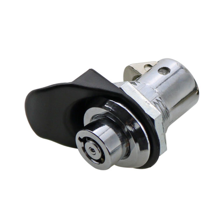
Different cam latches can look similar from the front while requiring different cutouts, retaining parts, cam positions, and assembly sequences. Start by identifying the complete model configuration and drawing revision.
- Operator or head: key, tool, knob, wing, or another project-specific operating style.
- Latch housing: the through-panel body that carries the operator and rotating shaft.
- Anti-rotation feature: flats, tabs, keying, shoulders, or a shaped housing profile that prevents the body from turning in the panel.
- Mounting retention: nut, spring clip, snap feature, screws, or another model-specific method.
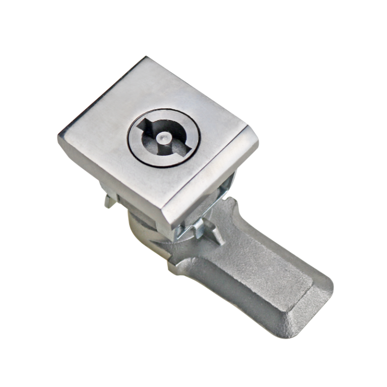
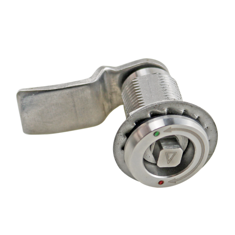
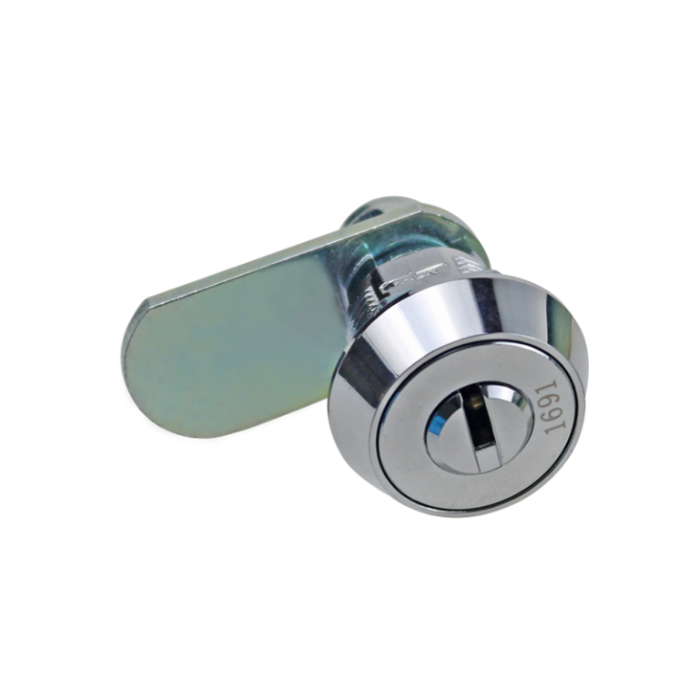
- Cam: straight or offset arm that turns behind the frame lip or keeper.
- Cam retention: screw, nut, washer, clip, formed end, or another controlled retaining method.
- Optional sealing parts: flange gasket, O-ring, washer, or other parts supplied for the specific installation.
- Keeper or frame lip: the structural surface engaged by the cam in the locked position.
Do not substitute parts from another model simply because they fit the shaft. A different cam thickness, offset, washer stack, or retaining screw can change engagement, rear clearance, and the locked position.
Review current cam latch models only after the cabinet interface and installation requirements are defined.
Confirm the Approved Installation Drawing Before Cutting
The latch model, grip range, cam length, and rear-clearance fit should already be approved before installation begins. At this stage, the installer verifies that the released drawing, received parts, panel stack, and cabinet assembly still match that approved configuration. Do not use the installation operation to reselect the latch or compensate for an unresolved fit problem.
| Approved Field | Installation Verification | Stop and Escalate If |
|---|---|---|
| Exact model and drawing revision | Match the received latch, cam option, retention hardware, and BOM to the released drawing. | The model, revision, or supplied hardware differs from the approved package. |
| Approved panel cutout | Confirm the profile, orientation, datum location, and anti-rotation features before machining. | The production drawing uses a different hole shape or omits a required flat or tab. |
| Approved panel stack | Verify that coating, reinforcement, spacers, washers, and double-wall layers match the released assembly. | The actual clamped stack differs from the approved fit condition. |
| Approved cam and shaft arrangement | Check the cam part number, straight or offset orientation, shaft index, washer order, and locking direction. | The received cam or orientation cannot reproduce the approved locked and unlocked positions. |
| Approved rear envelope | Confirm that no wiring, rail, bracket, insulation, or later-added component enters the released cam sweep. | The installed cabinet layout creates a new interference. |
| Approved strike or frame-lip position | Verify the engagement surface on the assembled door, including hinge alignment and installed gasket. | The strike location no longer matches the released door position. |
| Approved mounting method | Confirm the nut, clip, screws, snap feature, washer sequence, and model-specific assembly instruction. | The specified retention method cannot fully seat the housing without panel distortion. |
Panel thickness, grip range, cam length, housing depth, and design-stage strike engagement belong in the separate cam latch fit and panel thickness verification step. This installation page only checks that the approved fit remains valid in the manufactured door and received hardware.
Transfer the Model Cutout to the Panel
Establish the cutout from a controlled drawing, approved template, CNC file, or verified first-article layout. Do not trace the visible flange or estimate the hole from the outside diameter of the latch.
- Identify the cabinet-door datum and the intended latch centerline.
- Confirm the locked rotation and the orientation of every anti-rotation flat or tab.
- Check clearance from the cutout to door bends, hems, reinforcements, windows, gasket channels, and adjacent hardware.
- Confirm that the rear cam sweep remains clear through the full operating rotation.
- Mark or program the exact cutout profile and its datum relationship.
- Use a sample coupon or first article where the panel process, coating, or keyed profile is not yet proven.
Round Cutout vs. Anti-Rotation Cutout
A round hole may be correct for a model that uses a separate anti-rotation tab, bracket, or clamping feature. For another model, a D-flat, double-flat, tabbed, or keyed cutout may be essential. Removing that profile can allow the complete housing to rotate when the operator is turned.
Do not convert a shaped cutout into a round hole to simplify fabrication unless the latch supplier and cabinet design approve another positive anti-rotation method.
Cut and Finish the Panel Opening
The cutting method depends on panel material, thickness, coating, production volume, required profile, and available equipment. The installation requirement is the finished opening, not a particular universal tool.
- Verify that the equipment is isolated and the work area is clear of internal components that could be damaged by cutting or debris.
- Create the cutout using a process suitable for the panel material and required profile.
- Control burrs, edge rollover, local stretching, and distortion around the opening.
- Deburr both sides without removing the anti-rotation geometry or enlarging the cutout beyond its controlled limit.
- Restore project-required corrosion protection on exposed metal edges.
- Remove chips, abrasive residue, oil, and conductive debris from the door and enclosure.
- Verify the cutout with a gauge, template, or the actual latch housing before continuing assembly.
Do not force an oversized housing into an undersized opening and do not use the mounting nut to pull a distorted latch through the panel. Correct the cutout or fabrication process before assembly.
Install and Orient the Latch Housing
Install the housing in the orientation shown on the model drawing. Where a gasket, O-ring, washer, or spacer is supplied, maintain the specified order and seating surfaces.
- Set the operator in the specified reference position before orienting the housing.
- Fully engage the D-flat, double-flat, tab, or other anti-rotation feature.
- Seat the front flange or gasket evenly against the door surface.
- Install the retaining nut, clip, or screws without displacing the housing orientation.
- Use the model-specific mounting torque or assembly instruction where one is provided.
- If no controlled torque is available, mark the requirement as supplier confirmation required rather than applying a general value.
- Check that tightening has not bowed the panel, crushed a plastic wall, extruded the gasket, or damaged the coating.
Installation rule: additional mounting-nut torque is not a substitute for a correct grip range, keyed cutout, or panel reinforcement. If the housing turns or remains loose, inspect the interface before tightening further.
Set the Cam Orientation and Retention
The cam must clear the engagement surface when unlocked and move into full engagement when locked. Confirm the shaft index, cam offset direction, washer order, and retaining method before final tightening.
- Move the operator to the defined locked position.
- Place the straight or offset cam on the shaft in the orientation shown on the assembly drawing.
- Confirm whether the offset moves toward or away from the keeper plane.
- Install the specified washer, spacer, retaining screw, nut, clip, or formed-end feature.
- Verify that the retaining hardware does not prevent the cam from seating fully.
- Rotate to the unlocked position and confirm that the cam completely exits the keeper or frame lip.
- Check the complete rear sweep against wiring, rails, brackets, and other internal components.
Position the Keeper or Frame Engagement Surface
Some cam latches engage a separate keeper; others engage the enclosure frame lip directly. In either case, the contact surface must be located from the assembled door position, not only from nominal drawing dimensions.
- Confirm that the door is aligned on its hinges before setting the keeper.
- Install the door seal or gasket before establishing final cam engagement.
- Verify that the cam moves fully past the keeper edge rather than contacting only the corner.
- Confirm that the cam does not bottom out before the operator reaches the locked position.
- Check that the keeper or frame lip is stiff enough to react the closure load without bending.
- Make sure the cam does not pull the door sideways or change the intended door gap.
- For multiple latches, check that all cams reach their engagement surfaces without forcing one location to carry the complete load.
The allowable gap, cam overlap, and keeper position are model- and enclosure-specific. Confirm them from the latch drawing and cabinet assembly acceptance criteria rather than applying a universal clearance value.
Verify Door Closure and Gasket Contact
A standard rotating cam may pull a door against a frame, but that does not automatically provide a controlled compression stroke. Do not create sealing pressure by installing an excessively short cam, moving the keeper too far inward, or forcing the operator through the locked position.
- Confirm that the door contacts the gasket as intended before the cam reaches final engagement.
- Inspect the door and frame for bending while the latch is locked.
- Check whether operating effort rises because the cam is over-compressing the gasket or rubbing the keeper.
- Verify gasket contact around the complete door perimeter, not only near the latch.
- Treat enclosure sealing as an installed-system requirement involving the latch, cutout, gasket, door, frame, and enclosure joints.
If the project requires a defined pull-down stroke, repeatable gasket compression, or improved vibration retention, review the separate comparison of a cam latch or compression latch. The current page remains limited to installing a selected cam latch.
Cam Latch Installation Acceptance Check
Complete the inspection on the fully assembled door with the actual hinges, gasket, frame, keeper, and internal clearances.
| Check | Acceptance Question |
|---|---|
| Housing seating | Is the flange or housing shoulder fully and evenly seated against the panel? |
| Anti-rotation | Does the housing remain fixed while the operator is turned? |
| Panel condition | Is the panel flat, without cracking, coating damage, or mounting distortion? |
| Operator travel | Does the operator reach the intended unlocked and locked positions without forced overtravel? |
| Cam orientation | Does the cam move toward the keeper when locking and clear it completely when unlocking? |
| Cam engagement | Does the cam fully engage the keeper or frame lip without edge-only contact or binding? |
| Rear clearance | Is the complete cam sweep clear of wiring, rails, brackets, insulation, and other hardware? |
| Door alignment | Does locking avoid pulling the door sideways or changing the intended gap? |
| Gasket contact | Does the closed door meet the project-defined gasket-contact requirement without visible over-compression? |
| Retention | Are the housing and cam retaining features fully installed and secure? |
| Multiple-latch balance | Do all latch locations engage without one latch forcing another out of alignment? |
| Functional repeatability | Does the latch reproduce the same installed engagement through the project-defined functional check? |
Diagnose Cam Latch Installation Problems
| Symptom | Likely Installation Cause | Corrective Direction |
|---|---|---|
| Housing turns in the panel | Oversized cutout, missing anti-rotation flat, unseated tab, incorrect profile, or insufficient clamp. | Restore the correct keyed interface and verify panel support. |
| Housing remains loose | Panel stack is outside the model grip range, washer order is wrong, or the mounting feature is incomplete. | Confirm the complete thickness stack and model mounting method. |
| Cam misses the keeper | Wrong cam length, wrong offset direction, incorrect shaft index, or keeper mislocation. | Recheck the controlled assembly geometry. |
| Door will not close | Cam is too long, offset is reversed, keeper is too far inward, or the cam does not clear while unlocked. | Correct the cam orientation or engagement geometry. |
| Operator force is excessive | Gasket over-compression, cam rubbing, keeper misalignment, panel distortion, or incorrect cam offset. | Inspect door position and engagement rather than forcing the operator. |
| Door rattles when locked | Insufficient engagement, incorrect cam offset, flexible keeper, or door not seated against the intended surface. | Correct the keeper and cam relationship using project-specific acceptance criteria. |
| Cam strikes internal equipment | Rear sweep clearance was not checked through the complete rotation. | Change the cam, latch position, or internal layout. |
| Water or dust enters around the latch | Housing gasket, cutout finish, seating surface, or complete enclosure sealing has not been validated. | Inspect the installed sealing system; do not assume the latch alone provides the enclosure rating. |
Cam Latch Installation Workflow
- Confirm the exact latch model, cam option, mounting hardware, and drawing revision.
- Verify that the approved cutout, panel stack, cam geometry, strike position, and rear-clearance envelope match the manufactured door.
- Transfer the keyed cutout, datum location, anti-rotation orientation, and locking direction from the controlled drawing.
- Cut the panel opening, preserve the keyed profile, deburr both sides, remove debris, and restore required edge protection.
- Install the housing with the approved gasket, washer sequence, anti-rotation feature, and retention method.
- Set the straight or offset cam in the correct locked orientation, then install and secure the retaining hardware.
- Position the strike or verify frame-lip engagement with the hinges, gasket, and door in their final assembled condition.
- Verify door closure and gasket contact without forcing the operator, overloading the cam, or distorting the panel.
- Complete the installed acceptance check for housing seating, anti-rotation, cam engagement, rear clearance, door alignment, and repeatability.
Composite Engineering Scenario
This is a composite engineering scenario created to explain the installation logic. It is not a customer project record or product test claim.
An OEM is installing a quarter-turn cam latch in a coated steel control-cabinet door. The first article has three problems: the housing turns when the operator is used, the cam does not fully engage the frame lip, and the door bows near the latch when locked.
The review finds that the fabrication drawing replaced the model’s D-shaped cutout with a round hole. The mounting nut was tightened further to compensate, but the housing still lacked a positive anti-rotation interface. The cutout is corrected to match the controlled model profile.
The cam offset is also installed in the wrong direction. It moves away from the frame lip rather than toward it. After the cam is reoriented, it reaches the engagement surface, but the keeper has been positioned before the door gasket was installed.
With the gasket fitted, the door sits farther from the frame. The installer had moved the keeper inward and forced the latch closed, causing local panel distortion. The keeper is reset from the final assembled door position, and the housing clamp is returned to the model-specific assembly condition.
The corrected first article is then inspected for housing seating, anti-rotation, cam clearance, full keeper engagement, door alignment, gasket contact, retaining hardware, and repeatable operation. The installation is released only after the complete cabinet assembly meets the project-defined acceptance criteria.
FAQ
Do all cam latches use the same panel cutout?
No. Cam latch cutouts may be round, D-shaped, double-flat, tabbed, or otherwise keyed. The required profile and tolerance come from the exact model drawing. Changing a keyed cutout to a simple round hole can remove the anti-rotation function and allow the latch housing to turn in the panel.
Should the latch housing be installed before the cam orientation is set?
Install and secure the housing in its approved orientation first, then place the operator in the specified reference position and install the cam according to the assembly drawing. Setting the cam before the housing is fully seated can create an incorrect locked index or make the anti-rotation feature difficult to verify.
Which direction should the cam face when locked?
The cam must rotate into full engagement with the frame lip or keeper while clearing it completely in the unlocked position. The correct direction depends on the operator rotation, shaft orientation, straight or offset cam geometry, and whether the door is left- or right-hand. Confirm the locked position from the model drawing and assembly layout.
Why does the latch housing rotate in the panel?
Typical causes include an oversized cutout, a missing or incorrectly oriented anti-rotation flat, an unseated tab, insufficient mounting clamp, panel deformation, or use of a round cutout for a keyed housing. Correct the interface rather than relying only on additional nut torque.
Should the strike be positioned before or after the door gasket is installed?
Position or verify the strike with the door, hinges, gasket, and latch housing in their final assembled condition. Setting the strike before the gasket is installed can change the closed-door position and create insufficient engagement, excessive closing force, or local door distortion.
Can a cam latch provide an IP-rated seal?
A latch alone does not automatically give the complete enclosure an IP rating. Sealing depends on the installed latch housing, cutout, gasket, door, frame, enclosure joints, and test condition. If controlled gasket compression is required, evaluate whether a compression latch is more appropriate and validate the complete enclosure assembly.
Final Cam Latch Installation Check
A successful cam latch installation depends on the complete interface: the exact model cutout, total panel stack, grip range, housing seating, anti-rotation feature, cam orientation, keeper position, rear clearance, gasket condition, and retaining hardware.
Do not use generic hole sizes, universal keeper gaps, or unsupported mounting-torque values. Transfer the model drawing accurately, verify the installed door geometry, and inspect the latch in both locked and unlocked positions before releasing the panel or cabinet for production.
Contact HTAN for a cam latch interface review with the latch model, panel cutout, complete panel thickness, cam length and offset, door and frame section, keeper position, rear-clearance envelope, gasket condition, and required acceptance criteria.