HTAN is one of the leading manufacturers of industrial hinges, handles and latches in China.


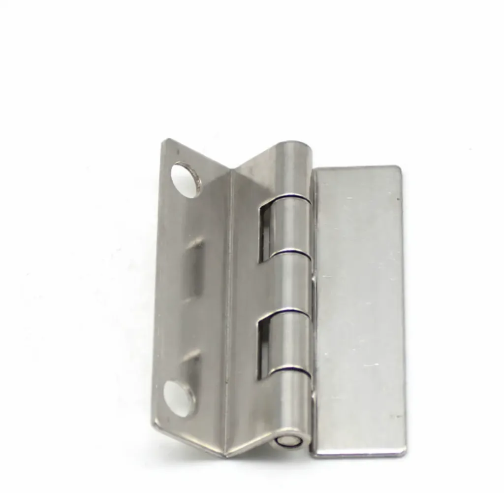
A stepped convex hinge is generally an industrial pin-and-knuckle hinge whose leaf profile is formed to bridge mounting surfaces that are not on the same plane. The step can move one mounting pad, the hinge barrel, or both away from a flat reference surface. The word convex usually describes the raised or outward-formed profile, but it does not establish one universal cross-section.
That distinction matters when a hinge is being identified from a photograph or selected for a new enclosure. Two parts may both be sold as stepped convex hinges while placing the pivot axis at different coordinates. The useful question is not whether the names match. It is whether the supplier drawing reproduces the required mounting-plane offset, hinge-axis position, door sweep, and load path.
Working definition: A stepped convex hinge uses a formed, raised, or offset leaf geometry to connect door-side and frame-side mounting regions that cannot be treated as one flat plane. It remains a free-swinging hinge unless the specified model adds another function such as lift-off, spring return, detent, friction, or a travel stop.
The Name Describes a Form, Not a Rating
Stepped convex hinge is not a single standardized product class with a fixed section, hole pattern, load capacity, or mounting direction. Industrial catalogs more often use terms such as stepped hinge, step hinge, formed hinge, or offset hinge. Those labels overlap, and manufacturers do not always apply them to identical geometry.
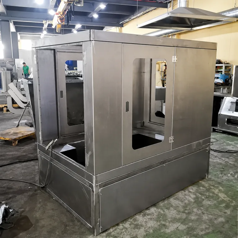
For example, TAKIGEN describes one stepped-hinge model as suitable for enclosures with steps. That statement identifies a product application, not a general rule for every hinge carrying the same name. Its dimensions and stated conditions remain specific to that model.
Other suppliers use offset pivot or offset hinge style for products that relocate the axis to improve access or clear formed sheet metal. A Southco offset-hinge example shows why function has to be read from the construction and drawing rather than inferred from the label.
The catalog name therefore does not prove that the hinge will carry a heavier door, distribute load equally, run silently, preserve a seal, or last longer than a flat hinge. Those outcomes depend on the complete hinge construction and the installed door system.
Follow the Two Mounting Planes
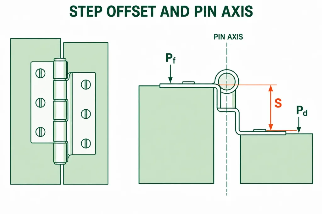
A section taken perpendicular to the hinge pin should show two physical mounting references: the frame-side plane and the door-side plane. Call them Pf and Pd. The signed normal distance between them is the required mounting offset, S. A positive or negative sign is useful because an outward step and an inward step are not interchangeable.
S is not automatically the door thickness, frame thickness, gasket thickness, or height of the visible embossment. It is the distance between the actual surfaces that seat the hinge after forming, reinforcement, coating, and any permitted shim are included. If one team measures from an outer cosmetic face while another measures from the hinge seating face, both can report a plausible number and still position the door incorrectly.
This single-value definition assumes that Pf and Pd are parallel across the hinge seating regions. If they are not parallel, one step dimension cannot fully locate the hinge. Define the angular relationship, local seating pads, and pin axis from a common datum reference frame.
| Geometry item | Attribute to control | Evidence that closes the question | Decision it supports |
|---|---|---|---|
| Frame mounting region | Plane, flatness, local thickness, and reinforcement | Enclosure section and mounting detail | Whether the fixed leaf seats without rocking |
| Door mounting region | Plane, return depth, coating, and backing | Production-intent door section | Whether the moving leaf reaches its intended datum |
| Step | Signed offset S and the datums used to measure it | Dimensioned hinge cross-section | Whether the leaves bridge the two planes |
| Pivot axis | Axis coordinates relative to both mounting planes | Pin-center location on the supplier drawing | Whether the door clears the frame through its swing |
| Attachment | Hole coordinates, fastener seats, weld zones, and access | Joint drawing and assembly method | Whether the hinge can be mounted repeatably |
This is the central test for the hinge family. If Pf and Pd are genuinely coplanar and no axis relocation is needed, a flat hinge may provide a simpler load path and an easier mounting joint. A step should solve a known geometric conflict rather than be selected as a visual preference.
Put the Hinge Axis in the Section View
The pin centerline is the functional rotation axis. It should be dimensioned from stable door and frame datums, not located indirectly by the outside edge of a barrel. Barrel diameter, leaf forming, knuckle clearance, and coating can all change while the required axis must remain in the same installed position.
At minimum, the section view should locate the axis in two perpendicular directions. One coordinate controls how far the axis stands away from the mounting faces. The other controls its position relative to the door edge, return, or frame opening. Together with S, those coordinates define the basic kinematic relationship. A nominal step height alone does not.
Door Sweep and Return Clearance
Every point on the rigid door section moves around the hinge axis. A return flange that clears in the fully closed view can strike a frame fold during the first few degrees of opening. A door that clears at 90 degrees can still touch trim, a gasket retainer, an adjacent cabinet, or the hinge leaf at an intermediate angle.
Review the closed position, at least one intermediate position, and the required full-open position using the production door section. Include the door return, hem, reinforcement, gasket, latch-side constraint, fastener heads, and neighboring structure. If the hinge has a formed profile, include its complete swept envelope rather than modeling only the pin.
An offset axis can move the door away from an obstruction, but more offset is not automatically better. Moving the axis outward can increase the space required around the enclosure, expose the barrel, change the gap at the hinge side, and increase eccentric loading on a thin mounting return.
What the Convex Form Actually Changes
The convex portion is usually a formed region that moves part of the leaf away from its original sheet plane. Depending on the design, it may create the step, clear a raised edge, house the barrel, or add local section depth. The supplier drawing should show which of those functions the form performs.
A raised form can make one local region less flexible than a completely flat strip, but the word convex does not prove structural capacity. Leaf thickness, material condition, bend radii, form width, grain direction where relevant, holes near bends, knuckle construction, pin support, attachment, and surrounding panel stiffness all affect the result. A deep form in thin sheet can still deform at its transition or pull a flexible mounting panel with it.
The forming process also creates dimensions that a flat outline cannot describe. Inside and outside radii, tangent locations, form height, angular condition, springback, and surface finish at the bends may influence fit. If the hinge is coated or plated after forming, the drawing must distinguish base-metal geometry from the delivered surface condition wherever the difference matters.
“Convex” should therefore be treated as a visual descriptor until the cross-section is available. A photograph can establish that the leaf is raised. It cannot establish the seating planes, axis coordinates, material condition, or allowable load.
A Hinge Can Bolt On and Still Be Wrong
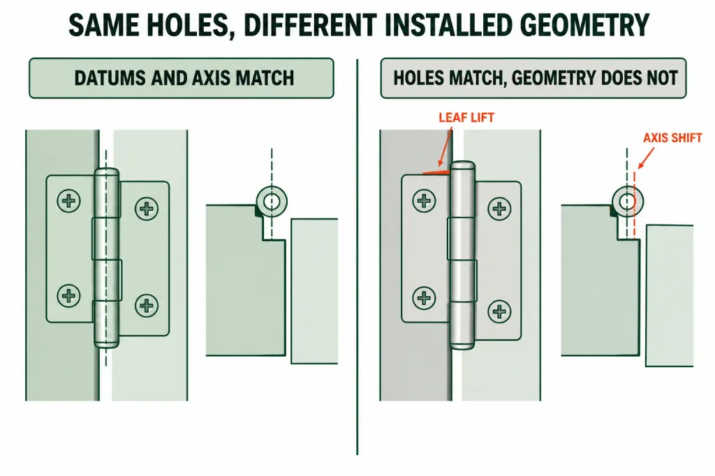
Consider a hypothetical enclosure whose door-side pad stands proud of the frame-side pad. A candidate hinge has the correct hole pattern and its catalog lists a step equal to the nominal panel offset. The supplier measures that step between uncoated leaf faces. The enclosure drawing, however, defines the offset between installed seating datums after a door backing plate and finish are present.
The hinge can be fastened without modifying a hole, yet its axis lands too close to the door return. Near the closed position, the return makes first contact with the frame and the operator has to pull the latch harder. A larger pin would not correct this condition. The first unresolved interface is the datum and stack-up used to place the axis.
| What appears to match | What can still differ | Installed consequence |
|---|---|---|
| Overall hinge outline | Leaf seating surfaces and formed-section depth | Leaf rocks, gaps, or distorts when tightened |
| Nominal step | Datum, sign, finish condition, and tolerance | Door sits too far in or out |
| Hole pattern | Axis position relative to the holes | Door sweep or closed gap changes |
| Barrel diameter | Pin, bore, knuckle length, and internal construction | Different play, friction, or wear behavior |
| Closed-position appearance | Intermediate-angle swept envelope | Door or hinge contacts the frame during travel |
The Step Can Add Eccentricity to the Load Path
The step does not remove the door load. The load still travels from the moving door structure into the door-side attachment, through the formed leaf and knuckles, across the pin and any bearing or bushing surfaces, then through the frame-side leaf and its attachment into the enclosure structure.
When a leaf is offset from its mounting plane, the force path may create local bending in the formed section, fastener joint, weld, backing plate, or sheet-metal return. Increasing the step can increase that eccentricity. A visually robust hinge may remain intact while the panel around its mounting holes deforms and moves the axis.
Door mass by itself cannot resolve this. The complete review also needs the loaded center of gravity, hinge quantity and spacing, mounting stiffness, opening stop loads, impact, vibration, and duty. The industrial hinge load capacity guide owns the full sizing and rating-evidence task. Here, the load question is limited to whether the stepped geometry creates a supportable installed load path.
Do not use the hinge as the door stop unless the product and assembly are explicitly designed and validated for that reaction. A stop impact applied through a stepped leaf can load a different section and direction from the static door weight used in a catalog reference.
Where Stepped Geometry Earns Its Place
A stepped form is useful when a real mounting or clearance condition prevents a flat leaf from seating correctly. Typical conditions include an inset door, a projecting frame flange, a formed door return, a reinforcement that changes the mounting level, or a hinge barrel that must stand clear of trim or a gasket-retaining feature.
| Application condition | What the step may solve | What remains to be verified |
|---|---|---|
| Inset access door | Bridges the frame and recessed door mounting levels | Axis location, edge gap, latch alignment, and opening sweep |
| Formed sheet-metal return | Moves a leaf or barrel past the fold | Bend clearance, seating area, and local reinforcement |
| Gasketed enclosure | Places the door relative to a seal line without stacking loose spacers | Compressed gasket position, latch action, and hinge-side contact |
| Raised trim or retainer | Provides local clearance around a projection | Full travel, fastener access, and neighboring equipment |
| Replacement of an existing formed hinge | Reproduces the original relationship between two mounting levels | Datums, step direction, axis coordinates, handedness, and wear-free dimensions |
In a gasketed enclosure, the hinge can establish position but it does not generate or regulate seal compression by itself. The gasket, door stiffness, hinge-side geometry, latches, stops, and frame all determine the final compression pattern. Selecting a deeper step to “improve sealing” without checking those interfaces can make the hinge side bottom out before the latch side reaches its intended condition.
Sometimes a Different Architecture Is Cleaner
Use a flat butt hinge when the mounting planes are coplanar, the barrel already clears the edges, and a direct leaf-to-structure joint is preferred. Use a purpose-designed offset hinge when moving the pivot axis is the main task and its mounting geometry fits the enclosure without an unnecessary leaf form. A concealed or corner hinge may be more appropriate when exterior projection, tamper access, or internal packaging controls the design. A lift-off arrangement addresses planned door removal, which is a separate requirement from mounting-plane offset.
Those names still do not make the final decision. The industrial hinge selection guide compares the broader motion, mounting, removal, environment, and load-path choices. This page stays with the narrower question of whether a stepped convex profile matches the required section geometry.
The Drawing Must Control the Functional Geometry
A purchasing description that says only “stepped convex hinge, stainless steel” leaves the critical interfaces open. The drawing or controlled specification should define the hinge in its installed coordinate system.
- Identify the door-side and frame-side seating planes and their datums.
- Dimension the signed step between those planes, including its tolerance and delivered surface condition.
- Locate the pin centerline from both mounting references and the relevant door or frame edge.
- Define leaf thickness, formed-section profile, bend radii where functional, knuckle arrangement, pin construction, and retention.
- Locate holes, slots, studs, or weld regions from the same functional datums used by the enclosure.
- State left-hand, right-hand, inside, outside, upper, or lower orientation where reversing the part changes the step or removal direction.
- Specify material and finish for the complete assembly, not only the visible leaves.
- Record the required opening range and any zones in which the door, hinge, fasteners, gasket, or adjacent structure must not interfere.
Use basic dimensions or another project-appropriate tolerance scheme only when the associated control and datum structure are clear. A tight plus/minus tolerance on the step does not compensate for an undefined seating plane or an axis located from a flexible cosmetic edge.
Replacement Parts Need Unworn References
When the original drawing is unavailable, do not copy only the visible hinge. Record the installed door and frame section before removal, support the door safely, and identify which surfaces actually seat the leaves. Measure the step and axis coordinates from unworn structural datums. Worn holes, bent leaves, compressed shims, thick repair coating, and door sag can make the removed part a poor master.
A supplier can reproduce a sample accurately and still reproduce its damage. Separate the intended geometry from the as-found condition, and mark every dimension that remains inferred rather than verified.
Prove the Motion on the Complete Door
Begin with a section study using the proposed hinge axis and production-intent door geometry. Then inspect a mounted sample with the actual attachment method, reinforcement, coating stack, gasket, latch, and neighboring structure. A loose hinge on a bench cannot prove the installed sweep or the stiffness of the mounting planes.
Move the door slowly from fully open toward closed and note the first interface that approaches or touches. Repeat from closed toward open. Direction matters because gasket drag, panel flexibility, fastener seating, and clearance can produce a different observation on the return stroke. Do not force the door past a tight point; doing so can erase witness marks or introduce damage that was not present at the start.
The sample review should establish:
- both leaves seat on their intended mounting surfaces without forced pull-down;
- the hinge axes remain aligned after final tightening or welding;
- the door return, frame, gasket retainer, fasteners, and hinge clear through the complete required travel;
- the closed gap, latch engagement, and seal position remain within the project requirements;
- the loaded door does not cause unacceptable local panel movement or loss of alignment;
- the removal direction and service clearance work as intended if the hinge is detachable.
Acceptance limits must come from the application, supplier evidence, and controlled project requirements. The hinge name does not supply universal values for allowable play, operating force, sag, gap, or cycle life.
Send the Cross-Section, Not Just the Hinge Name
For a model review, send a section through the hinge side in the closed position, the door and frame seating datums, required signed step S, required pin-center coordinates, door dimensions and loaded mass, hinge quantity and spacing, opening range, attachment method, gasket or trim envelope, material and finish requirements, and photographs of the actual mounting area. Mark which dimensions are fixed and which may change.
Review available constructions in the HTAN industrial hinge range. If a catalog drawing does not reproduce the required plane and axis relationship, submit the enclosure section through the project inquiry page so the geometry can be compared before a sample is selected.
Stepped Convex Hinge FAQ
What is a stepped convex hinge?
A stepped convex hinge is generally a pin-and-knuckle hinge with a formed or raised leaf profile that bridges door-side and frame-side mounting surfaces on different planes. The exact cross-section is not universal, so the step, seating planes, and hinge-axis coordinates must be taken from the product drawing.
Is a stepped convex hinge the same as an offset hinge?
Not necessarily. Both terms can describe geometry that separates mounting planes or relocates a pivot, and supplier terminology overlaps. An offset hinge may move the axis without using the same raised leaf form. Compare the cross-section, mounting datums, axis position, and motion rather than treating the names as interchangeable.
Does the stepped convex shape increase hinge load capacity?
The name alone does not establish a higher load capacity. Capacity depends on the complete leaf, formed section, pin, knuckles, internal bearing surfaces, attachment, hinge spacing, and door and frame structure. A step can also introduce eccentricity and local bending, so use model-specific evidence and the installed load path.
How should the step of a stepped hinge be measured?
Measure the signed normal distance between the actual frame-side and door-side hinge seating planes. State the datums, direction, tolerance, and whether the dimension applies before or after the specified finish. Do not assume the step equals panel thickness, gasket thickness, or the visible height of the formed profile.
Will a stepped convex hinge improve gasket compression?
It can place the door at a useful offset relative to the seal, but it does not control gasket compression by itself. Hinge-axis position, door stiffness, gasket geometry, latches, stops, frame condition, and manufacturing variation determine the compression pattern. Verify the complete closed-door assembly.
Can a stepped convex hinge replace a flat butt hinge?
Only if the stepped hinge reproduces the required mounting planes, axis coordinates, hole or weld locations, handedness, opening clearance, attachment strength, and door position. Matching overall size or hole spacing is not enough. If the original mounting surfaces are coplanar, a flat hinge may remain the cleaner choice.
What information should I send when requesting a stepped hinge?
Send a closed-position enclosure section, door and frame mounting datums, signed step, pin-center coordinates, door dimensions and loaded mass, hinge quantity and spacing, opening angle, attachment, gasket and trim envelope, material, finish, handedness, and photographs. Identify which dimensions are controlled and which remain open for supplier input.