






Industrial hinges, handles and latches for OEM equipment.
- +86 13720060320


Countersunk vs Through-Hole Hinge Mounting: Fastener Fit, Leaf Thickness, and Drawing Callouts
A flush screw head does not prove that the hinge leaf is clamped.
The screw can sit level with the hinge surface while contacting only the outer rim of an incorrect countersink. It can also bottom in a threaded insert before the leaf reaches the mounting panel. A straight clearance hole avoids the tapered seat, but it changes head projection, bearing area, adjustment freedom, and rear-side access.
A countersunk vs through-hole hinge mounting decision therefore starts with the complete fastened joint: screw head, hinge leaf, mounting panel, thread or nut, available clearance, coating, and the surface that must remain flush.
This page assumes that bolted attachment has already been selected. Projects still deciding between welding and removable fasteners should begin with the weld-on versus bolt-on hinge decision. The broader frame load path, fastener retention, slots, shims, and system-level vibration behavior remain with the bolt-on machine-frame door hinge mounting guide. This page owns one narrower task: selecting and specifying the hole and fastener-seat geometry in the hinge leaf.
Start With the Mounting Stack-Up
Do not choose a countersink from the hinge drawing alone. Lay out the joint from the top of the screw head to the end of the thread.
- Fastener head: head style, diameter, included angle, drive recess, and allowable projection.
- Hinge leaf: material, thickness, flatness, hole location, and any nearby bend or knuckle.
- Mounting surface: sheet, plate, extrusion, tube wall, bracket, or reinforced frame pad.
- Thread support: tapped plate, weld nut, rivet nut, threaded insert, loose nut, or through-bolt arrangement.
- Rear envelope: tool access, nut access, thread projection, cables, liners, seals, and internal equipment.
- Surface condition: paint, powder coating, plating, burrs, protective film, and any gasket beneath or beside the hinge.
The requirement for a flush exterior is only one input. The joint still needs enough leaf material around the hole, a compatible screw seat, usable thread engagement, and a clear load path into the mounting structure.
Terminology boundary: a countersunk mounting hole normally includes a through clearance hole plus a conical seat. In this article, “through-hole” means a straight clearance hole without a countersink, counterbore, or spotface.
Countersunk vs Through-Hole Hinge Mounting
A countersunk seat is useful when the fastener head must remain flush with or below the hinge surface. A straight clearance hole is usually the better starting point when head projection is acceptable and the joint benefits from a larger bearing surface, a washer, simpler hole manufacture, or more assembly freedom.
| Joint Requirement | Countersunk Seat | Straight Clearance Hole |
|---|---|---|
| Screw head must not project above the leaf | Usually appropriate when the head and seat geometry are matched | Requires a low-profile alternative or accepts head projection |
| Thin hinge leaf | May remove too much local section or create a knife edge | Preserves the full leaf thickness around the hole |
| Washer or broad head bearing | Normally incompatible with a standard flat washer on the same face | Allows a washer or larger bearing head when space permits |
| Assembly adjustment before tightening | The tapered head tends to center the fastener in the seat | Clearance can permit controlled positioning before clamp-up |
| Rear nut or through-bolt | Possible, but head-seat compatibility and rear access still govern | Common where both sides remain accessible |
| Head projection at mating or moving surfaces | Supports a flush outer surface when the seat and head are correctly matched | Head height must be checked against adjacent parts and through the full hinge motion |
| Replacement fastener control | Replacement screw must match the specified head form, angle, diameter, grade, and length | Head or washer options may change only within the specified bearing, strength, clearance, and envelope limits |
The table is only a first screen. Leaf thickness, head angle, edge distance, mounting access, and the production drawing decide whether either option is buildable.
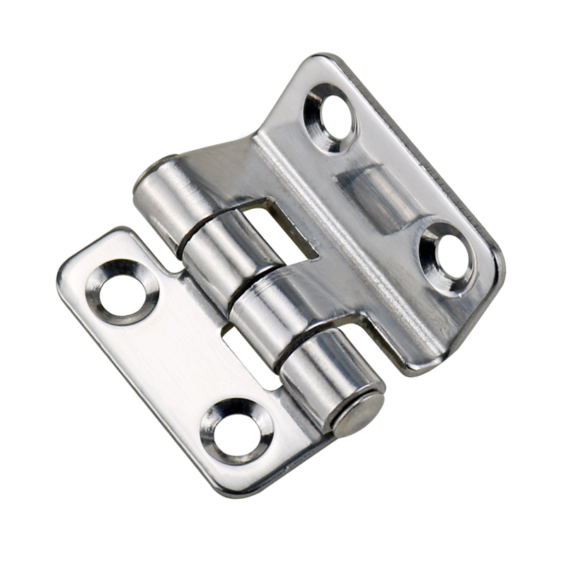
Countersunk Seat Example
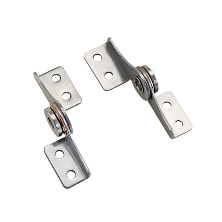
The hinge model below is used only to show the conical mounting-hole form. Its overall leaf shape, knuckle arrangement, and size should not be compared directly with the straight-hole example.
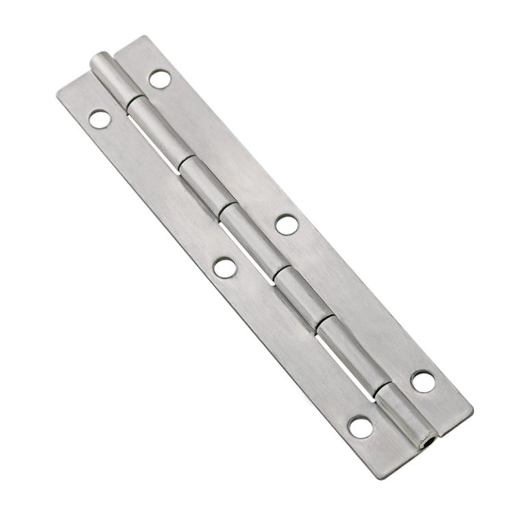
Straight Clearance-Hole Example
This second model shows a straight clearance hole without a conical seat. Head projection, washer coverage, nut access, and rear clearance still depend on the complete mounting stack-up.
Fastener Head and Seat Geometry
Select the fastener standard and head geometry before releasing the countersink. “Flat-head screw” is not enough. The drawing or specification should establish the head form, included angle, nominal size, drive type, and the permitted relationship between the head and the hinge surface.
The head and countersink need broad, stable contact. When the included angles differ, the head may touch near the outer rim or near the small end of the seat instead of distributing load across the intended surface. A visibly flush head can still be poorly seated.
A multi-hole pattern adds another constraint. Each countersunk head attempts to center in its own seat. If the hinge and mounting-panel patterns do not match, one screw can seat while another lifts the leaf or contacts only one side of the countersink. Straight clearance holes usually permit more positional adjustment before tightening. Countersunk patterns therefore require tighter control of hole position, seat concentricity, and the mating thread pattern.
- Countersink angle: match the fastener-head geometry specified for the project.
- Major diameter: large enough to seat the head, but not so large that it approaches the leaf edge or adjacent feature.
- Depth or flush condition: define whether the head may sit proud, flush, or below the leaf surface.
- Clearance diameter: provide the intended fit without allowing the head to mask an oversized or misplaced hole.
- Seat concentricity: control the relationship between the conical seat and the through clearance hole when eccentricity could create one-sided head contact.
- Entry edge: remove burrs without changing the functional seat.
- Coating: account for buildup that can change seating, alignment, and measured head height.
ISO 10642:2026 specifies the characteristics of metric hexagon-socket countersunk-head screws with reduced loadability due to head design. ISO 273:1979 provides fine, medium, and coarse clearance-hole series for general-purpose bolts and screws. These standards define fastener or clearance-hole geometry; they do not select hinge-leaf thickness, countersink side, edge distance, screw length, thread engagement, mounting-panel strength, or project acceptance criteria. If another countersunk-head family is used, reference the applicable product standard for that head form.
Leaf Thickness Below the Countersink
The local section beneath a countersunk seat is the original leaf thickness minus the material removed by the seat. This is a geometry check, not a universal minimum-thickness rule.
A larger screw head or deeper seat can leave a thin annular section around the clearance hole. Manufacturing tolerance can make the condition worse: a leaf at its minimum thickness and a countersink at its maximum depth may leave far less material than the nominal drawing suggests.
- Check the minimum leaf thickness, not only the nominal value.
- Review the maximum permitted countersink depth or diameter.
- Inspect whether the seat breaks through and creates a sharp or fragile edge.
- Confirm that tightening does not dish, crack, or permanently indent the leaf.
- Check whether the screw head reaches the required flush condition before the remaining section becomes inadequate.
- Include forming, polishing, grinding, and coating effects where they change local thickness or seating.
A thicker leaf can provide more countersink depth, but leaf thickness also belongs to the broader hinge load and durability decision. That separate task is covered in the industrial hinge leaf-thickness guide.
Thin-leaf alternative: when a full countersink removes too much local section, review a straight clearance hole, a low-profile noncountersunk fastener, a locally thickened mounting feature, or a revised leaf thickness. The correct option is project-specific.
Edge Distance and Local Bearing
For a countersunk hole, edge distance should be reviewed from the large seat diameter as well as from the clearance hole. A clearance hole can appear safely inside the leaf while the countersink nearly reaches the outer edge, a bend tangent, or the knuckle transition.
Inspect the actual geometry around every hole:
- Net material from the countersink major diameter to the leaf edge.
- Distance to adjacent holes, slots, bends, reliefs, welds, and knuckles.
- Flat seating area between the hinge leaf and mounting panel.
- Head or washer bearing area available on the selected face.
- Whether the mounting panel can support the local clamp and service load.
- Whether a countersink or washer overlaps a formed radius or uneven coating.
Do not assign one universal edge-distance ratio to every hinge. Fastener size, leaf material, panel material, hole process, service load, vibration, and the surrounding frame section all influence the acceptable geometry. This page reviews the hole region; the complete structural load path belongs to the bolt-on mounting guide.
Access Behind the Mounting Panel
A straight clearance hole is not automatically easier to maintain. Serviceability depends on the complete fastening arrangement.
A loose nut may be practical during initial assembly and impossible to reach after cables, liners, insulation, or internal equipment are installed. A rivet nut allows one-sided access but introduces its own grip-range, rotation, pull-out, and replacement questions. A tapped plate avoids a loose nut but requires adequate thread depth and protection against screw bottoming.
- Can the installer hold the nut or insert during final assembly?
- Can the same fastener be removed after the equipment is fully populated?
- Does the screw project into a cable, seal, insulation layer, or moving component?
- Can a replacement screw be inserted on the required axis?
- Will repeated removal damage a thin threaded feature or rotate an insert?
- Does the chosen head style allow the required installation tool clearance?
The hole form and the rear attachment must be released together. A drawing that shows only the hinge leaf cannot prove the joint is serviceable.
When a Flush Screw Head Still Does Not Clamp
The flat-head screw appears flush, and the torque tool reaches its target. The hinge still shifts during a vibration check. Inspection shows that the head contacted only the outer rim of the countersink because the head and seat angles did not match. At another hole, the screw bottomed in the threaded insert before the hinge leaf reached the panel.
The assembly looked complete, but clamp load never reached the full hinge interface. The corrective review must include head seating, screw length, thread depth, leaf-to-panel contact, coating, burrs, and the actual gap after tightening.
This is an illustrative engineering scenario, not a customer project record or product test claim.
Useful inspection evidence includes a contact witness on the countersunk seat, a depth check, screw-length and thread-depth comparison, feeler-gauge inspection beneath the leaf, and repeat measurement after final tightening. A target torque value by itself does not prove that the intended surfaces were clamped.
Drawing Callouts for the Hinge Leaf
The drawing should make the intended seat reproducible and inspectable. Avoid a generic note such as “countersink for flat-head screw” without the fastener basis or accepted head position.
| Drawing Field | Countersunk Mounting Hole | Straight Clearance Hole |
|---|---|---|
| Hole diameter | Specify the through clearance diameter | Specify the selected clearance-hole diameter or approved series |
| Seat geometry | Major diameter and included angle, or an equivalent controlled callout | State that no countersink, counterbore, or spotface is intended where ambiguity exists |
| Head position | Define permitted proud, flush, or below-surface condition | Define available head height and surrounding clearance when critical |
| Seat side and orientation | Identify the countersunk face in a section view or with a controlled “CSK THIS SIDE” callout | Identify installation orientation and the required deburring condition on each face |
| Fastener basis | Identify the applicable head form, standard, and nominal size | Identify fastener size, head or washer condition, and rear attachment |
| Hole location | Locate from functional datums that connect the pattern to the hinge axis and mounting interface | Use the same functional datum logic |
| Edge condition | Control burr removal without altering the functional conical seat | Control burrs and sharp edges on both sides as required |
| Inspection | Define the gauge, depth, flushness, or head-seat check needed for critical applications | Define hole-size and position checks; include washer coverage or bolt fit where relevant |
Counterbore and spotface callouts should remain separate from countersink callouts. A cylindrical recess does not provide the same seating geometry as a conical countersink. Mixing these terms can lead the supplier to manufacture a different fastener interface from the one the designer intended.
Validate the Complete Fastened Joint
A loose screw placed into a loose hinge can show obvious geometry errors. It cannot prove the installed clamp condition.
Use the production-intent hinge leaf, fastener, mounting panel, threaded support or nut, finish, washer where applicable, and final tightening method. Then inspect the joint in the state in which the equipment will operate.
| Validation Check | Evidence to Record | Reason |
|---|---|---|
| Head position | Proud, flush, or recessed condition measured against the drawing requirement | Confirms clearance and appearance without assuming clamp quality |
| Head-seat contact | Contact witness, gauge result, or inspected seating pattern | Detects angle mismatch and rim-only contact |
| Leaf-to-panel contact | Visual or feeler-gauge check after final tightening | Detects screw bottoming, burrs, coating interference, or local distortion |
| Local deformation | Leaf dish, cracking, indentation, finish damage, or edge breakout | Shows whether the hole region tolerates assembly load |
| Motion clearance | Full hinge travel with the installed screw heads and surrounding parts | Confirms that the chosen head height does not create interference |
| Service access | Tool, nut, insert, and screw removal access in the completed equipment | Confirms maintainability of the released attachment |
| Post-exposure movement | Witness marks, gap, slip, or fastener condition after project-specific use or vibration | Shows whether the complete joint retains its intended condition |
This check validates the mounting interface, not the full machine door. Door sag, frame flexibility, latch alignment, cable resistance, and repeated operating exposure require complete assembly validation after the hinge and attachment geometry are fixed.
Send the Mounting Detail
Provide the hinge-leaf thickness and material, intended screw standard and size, required head position, mounting-panel section, thread or nut arrangement, rear access, finish, hole pattern, and any interference-critical surfaces. HTAN can use those inputs to discuss suitable mounting-hole and hinge configurations for the project.
FAQ
Can a countersunk hinge hole be changed to a straight through-hole?
Yes, but the change affects screw-head projection, bearing area, washer use, assembly adjustment, surrounding clearance, and possibly the fastener or rear attachment. Review the complete mounting stack-up before changing the drawing.
How thick must a hinge leaf be for a countersunk screw?
There is no universal thickness. The required leaf depends on screw-head geometry, countersink depth and tolerance, remaining local section, edge distance, hinge material, mounting-panel support, and the project load and acceptance criteria.
Why does a countersunk screw sit above the hinge surface?
Possible causes include an undersized or shallow countersink, a mismatched head angle or diameter, coating buildup, burrs, the wrong fastener standard, or incomplete seating caused by alignment or thread conditions.
Can a washer be used with a countersunk hinge hole?
A standard flat washer is normally used with a noncountersunk bearing surface, not between a countersunk head and its conical seat. Special systems exist, but the washer, head, seat, and available space must be specified as one compatible arrangement.
Should the hinge drawing specify the screw standard?
Yes when head geometry, fit, flushness, strength, or interchangeability matters. At minimum, identify the nominal size and head form; critical projects should reference the applicable fastener standard and accepted head position.
A countersunk vs through-hole hinge mounting decision is ready for release when the screw head, leaf thickness, hole geometry, edge condition, rear attachment, and drawing callouts all describe the same complete fastened joint.