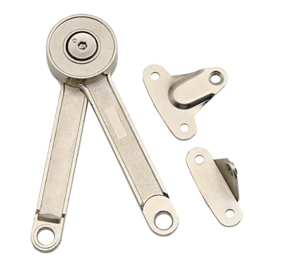
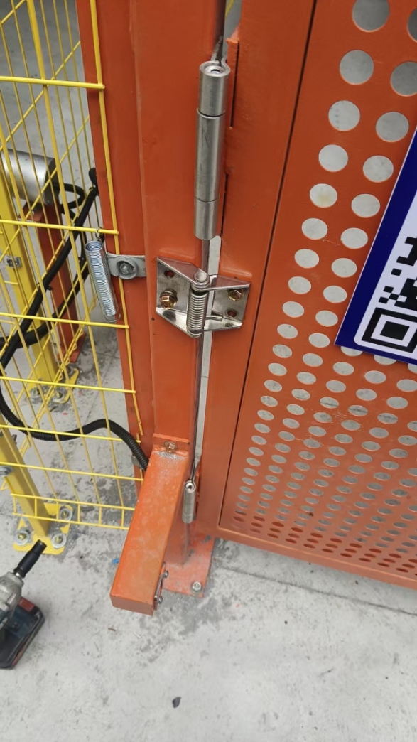
HTAN is one of the leading manufacturers of industrial hinges, handles and latches in China.


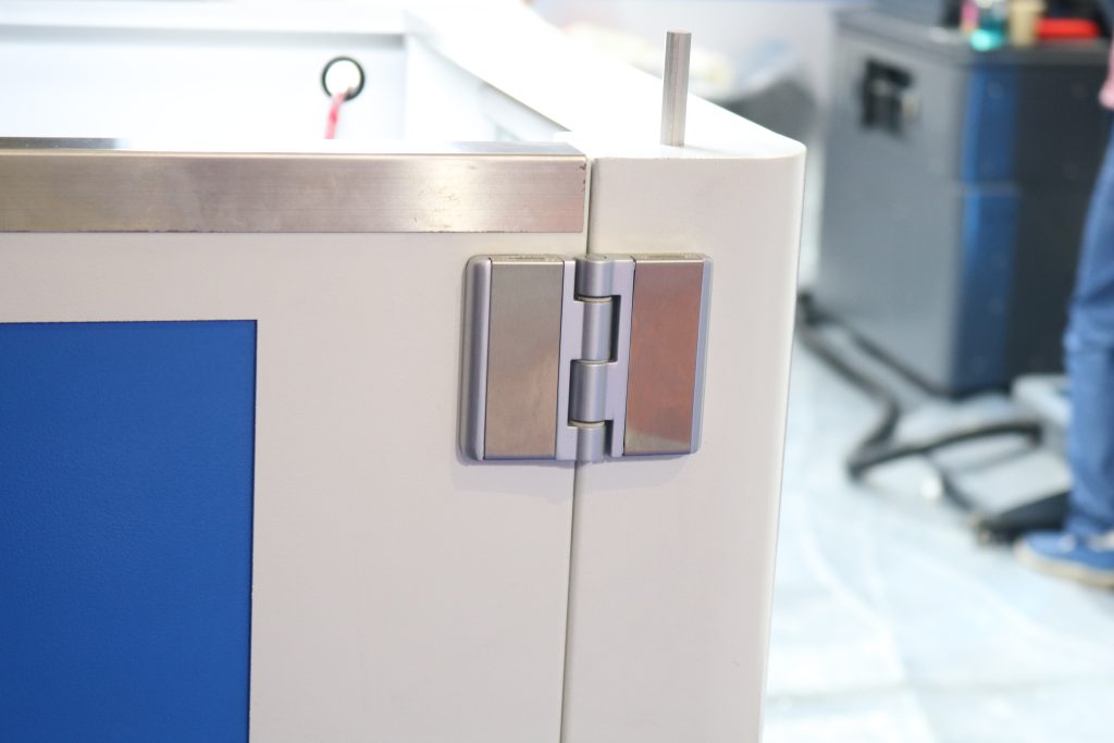
Electrical enclosure hinge architecture is the relationship between the hinge axis, door, frame, mounting surfaces, and removal method. It determines how the door clears the enclosure return, whether the hinge occupies internal or external space, how the door can be removed, and how loads reach the cabinet structure.
The architecture should be selected before choosing a specific hinge model or material. A corrosion-resistant hinge can still be the wrong mechanism if its pivot axis causes the door to strike an adjacent cabinet, its concealed body conflicts with internal equipment, or its lift-off direction cannot be used at the installation site.
This guide helps enclosure designers choose between external, concealed, fixed, offset, and removable arrangements. After the mechanism is selected, material, corrosion, sealing, detailed dimensions, and supplier requirements can be reviewed against the final enclosure design.
Architecture first: define the door-to-frame geometry, pivot location, opening envelope, and removal requirement before comparing materials, finishes, or catalog dimensions.
Start With the Electrical Enclosure Door and Frame Section
A front view rarely contains enough information to select the hinge architecture. The critical decisions appear in the hinge-side cross-section: door skin, formed return, frame flange, gasket land, stiffener, mounting access, and the space available for the pivot and moving leaves.
| Required Input | Why It Changes the Architecture | Action Before Model Selection |
|---|---|---|
| Door relationship to frame | Overlay, partially inset, and flush doors require different offsets and pivot positions. | Provide a hinge-side section in the closed position. |
| Door and frame returns | Formed flanges can block internal leaves, pins, nuts, or the opening path. | Mark the full return depth and bend radii. |
| Gasket land | The hinge must avoid damaging the sealing surface and allow the door to release and close consistently. | Show the gasket location and the uninterrupted sealing land. |
| Internal equipment envelope | Concealed hinges and mounting hardware consume space inside the enclosure. | Show keep-out zones for rails, wiring, devices, and cable ducts. |
| External clearance | Exposed hinge bodies and the door sweep may conflict with walls, neighboring cabinets, or guards. | Define the available side and rear clearance. |
| Door removal requirement | A removable door changes pin orientation, lift direction, service space, and handling. | State whether the door must remain captive or be removable without hinge disassembly. |
| Mounting access | Bolts, nuts, studs, welds, and tools need access during assembly and service. | Identify which surfaces are accessible before and after the cabinet is populated. |
Do not begin with a request such as “use a concealed hinge” or “use a stainless hinge.” Those statements describe one preference, not the complete mechanism. The section drawing reveals whether that preference can be integrated without changing the door return, frame, latch position, or equipment layout.
Choose an External or Concealed Pivot Location
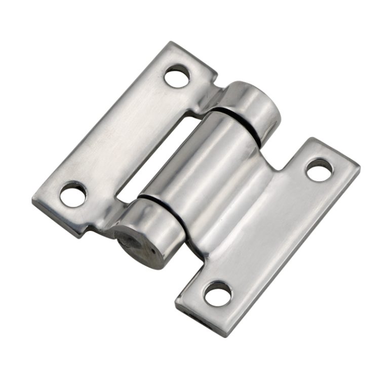
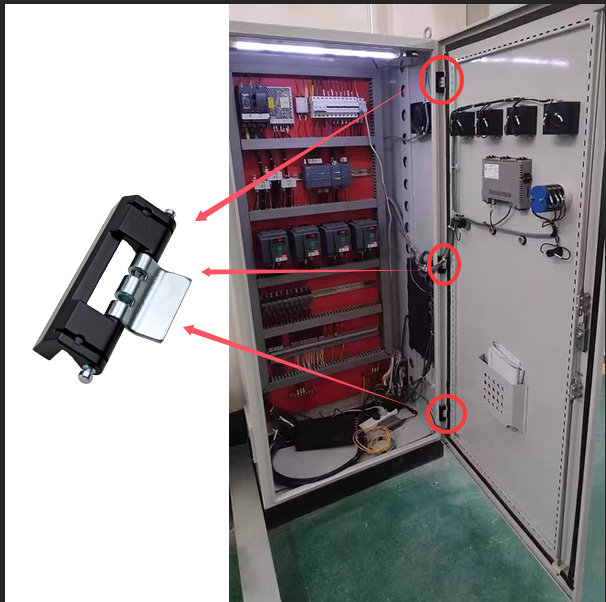
The first architecture decision is where the pivot and hinge body should sit relative to the enclosure boundary. External hinges place most of the mechanism outside the cabinet. Concealed hinges place the operating mechanism behind the closed door or within the door-and-frame return.
| Architecture | Strong Starting Conditions | Critical Limits to Check |
|---|---|---|
| External surface-mounted hinge | Direct load path, visible mounting access, simple inspection, limited internal clearance, or robust industrial construction. | External protrusion, snag exposure, tamper access, side clearance, and appearance. |
| External offset or corner hinge | The pivot must project around a formed door return, raised edge, or frame corner. | Door sweep, offset bending, fastener access, and the load created by the projected axis. |
| Concealed internal hinge | Clean exterior, reduced external projection, protected hardware, or tighter external equipment layouts. | Internal keep-out space, return-flange interference, restricted opening geometry, mounting access, and service inspection. |
| Multi-link concealed hinge | The door edge must translate away from a frame return before rotating, or a wide opening is needed without an external pivot. | Linkage envelope, tolerance sensitivity, stiffness, free play, and interference through the full motion. |
An external hinge is often easier to integrate because the pivot axis can be placed outside the door and frame sections. The load path from the door leaf into the frame is also easier to inspect. The tradeoff is visible hardware and a larger external envelope.
A concealed hinge removes the external projection but does not remove the space requirement. It moves that requirement inside the cabinet, where the hinge body and moving links may conflict with rails, wiring, latches, gasket returns, or a door stiffener. For concealed-hinge-specific dimensions and installation geometry, use the industrial cabinet concealed hinge guide.
Decide Whether the Electrical Enclosure Door Must Be Removable
Door removal is an architecture requirement, not a convenience to add after the hinge has been selected. A lift-off or removable arrangement can improve wiring access, equipment installation, coating, transport, and field replacement, but it also introduces a specific removal direction and handling procedure.
- Use a fixed or captive hinge when the door must remain attached during service, loss of the door would create a safety or handling problem, or cables and bonding conductors remain permanently connected.
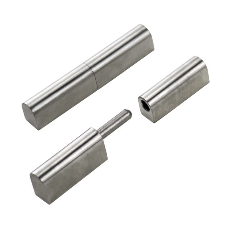
- Use a lift-off architecture when the complete door must be removed repeatedly without disassembling the hinge leaves.
- Use a removable pin or retained pin when occasional removal is required but uncontrolled lift-off during normal use is not acceptable.
Before approving a lift-off design, check the door mass and handling method, vertical or axial lift clearance, the angle at which removal is possible, the possibility of accidental disengagement, and the routing of bonding straps, switches, fans, displays, or wiring attached to the door.
Use the removable hinge guide to compare lift-off direction, pin retention, removal clearance, and service handling after the enclosure has been identified as requiring a removable door.
Match the Hinge Architecture to Overlay, Inset, or Flush Doors
The door relationship to the frame determines how the hinge axis must move the hinge-side edge. A model that works on an overlay door may bind on a flush door because the door edge must clear a different frame corner and gasket return.
| Door Construction | Architecture Implication | Geometry to Verify |
|---|---|---|
| Overlay door | An external surface hinge is usually straightforward; a concealed hinge needs an internal offset or link path that moves the door around the frame. | Overlay amount, return depth, gasket release, and side sweep. |
| Partially inset door | The pivot may need to sit close to the door edge or use an offset to clear both the frame and door return. | Closed gap, edge clearance, link interference, and opening angle. |
| Flush or fully inset door | The hinge must rotate within or translate out of the frame opening without scraping the return. | Pivot projection, door-edge radius, internal clearance, and stop location. |
| Double-return or stiffened door | The added section improves stiffness but can block leaves, nuts, pins, and concealed link movement. | Mounting surface width, tool access, local reinforcement, and moving envelope. |
| Gasketed formed door | The architecture must allow the gasket to release during opening and return to the same closed position. | Gasket land, compression direction, hinge-side gap, and latch coordination. |
Evaluate the closed section and several intermediate angles, not only the fully open position. Most hinge-side clashes occur during the first part of opening, when the door return, gasket, and frame corner are still close together.
Check the Door Sweep and Adjacent Cabinet Clearance
The pivot-axis location controls more than the maximum opening angle. It determines the path of the latch edge, the movement of the hinge-side edge, and the space occupied by the complete door while it opens.
- Adjacent cabinets: confirm that the door and exposed hinge do not strike the neighboring enclosure, handles, roof, plinth, or side panel.
- Walls and guards: verify the required service angle when the enclosure is installed near a wall, machine frame, fence, or aisle barrier.
- Operator space: check that the open door does not block controls, emergency access, or the technician’s working position.
- Internal motion: for concealed and multi-link hinges, sweep the complete hinge body, leaves, links, and fasteners through the motion.
- Removal space: a lift-off door may need vertical clearance in addition to the rotational opening envelope.
A CAD motion check is useful, but it must use the actual formed sections, fastener heads, cable routes, gasket, and surrounding equipment. A simplified pivot line can miss an interference caused by a return flange or concealed link.
Assign the Load Path and Mounting Method
After the pivot and removal architecture are defined, determine how the door load reaches the enclosure structure. The load path should pass from the door skin or stiffener into the hinge leaf, through the pin or linkage, into the frame-side leaf, and then into a reinforced frame section.
Load path: Door panel or stiffener → door-side hinge attachment → pin or linkage → frame-side attachment → enclosure frame.
A hinge mounted only to thin sheet can deform the local panel even when the hinge body itself is strong enough. Check the door center of gravity, hinge spacing, local sheet stiffness, fastener pattern, reinforcement, and the moment produced by any offset between the load and the mounting surface.
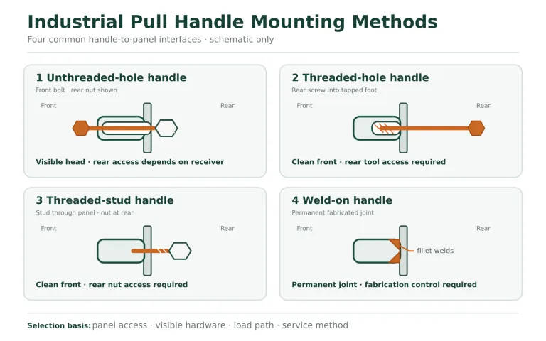
Bolted or screwed mounting supports replacement and avoids welding heat, but it requires hole control, tool access, and a retention method suitable for the service environment. Welded mounting can create a direct structural connection, but weld sequence, distortion, coating repair, and service replacement must be considered. These are mounting decisions within the chosen architecture; they should not be used to compensate for an incorrect pivot location.
Coordinate the Hinge With the Gasket and Latch System
The hinge positions the door; the latch pulls and holds the door against the frame; the gasket reacts against both systems. These parts must be reviewed as one door-closing geometry even though their detailed selection belongs to separate pages.
- Preserve the gasket land: do not place leaves, studs, welds, or cutouts where they interrupt the intended sealing surface.
- Control hinge-side position: free play, bracket flex, or a poor axis location can change the hinge-side gap and latch engagement.
- Allow gasket release: the door should move away from the compressed gasket without rolling, tearing, or scraping it against the frame return.
- Coordinate latch locations: the latch system must close the door without forcing the hinge to correct a misaligned frame.
- Validate the complete enclosure: a hinge model by itself does not carry an IP rating for the assembled cabinet.
For detailed gasket reaction, sealing tolerance, and enclosure-level validation, use the guide to hinge selection for IP65/IP67 cabinets after the pivot and door-closing geometry have been established.
Compare Electrical Enclosure Hinge Architectures
Use the matrix after the door and frame sections have been defined. It is a starting decision, not a substitute for a motion check and prototype.
| Project Condition | Preferred Starting Architecture | Main Reason | Required Verification |
|---|---|---|---|
| Limited internal space and easy exterior access | External fixed hinge | Keeps the mechanism outside and provides a direct, inspectable mounting path. | External projection, sweep, tamper exposure, and adjacent clearance. |
| Clean exterior and protected hardware | Concealed internal hinge | Removes visible leaves and pins from the enclosure face. | Internal keep-out zone, return interference, mounting access, and opening angle. |
| Door edge must move away before rotating | Offset or multi-link architecture | Creates translation or projected pivot clearance around the frame return. | Linkage stiffness, free play, full motion envelope, and tolerance sensitivity. |
| Door must be removed frequently | Lift-off or controlled removable hinge | Allows door removal without dismantling both hinge leaves. | Lift clearance, handling, disengagement prevention, and connected cables or straps. |
| Door must remain captive | Fixed-pin or retained-pin hinge | Prevents unintended separation during service or operation. | Service procedure, pin retention, replacement access, and door support. |
| Heavy formed door with direct structural support available | External or reinforced fixed architecture | Provides a short, visible load path into the frame. | Door CG, hinge spacing, reinforcement, fasteners or welds, and frame deflection. |
| Tight side clearance between cabinet rows | Concealed or carefully offset architecture | Can reduce external hardware projection and control the sweep. | Actual moving envelope at intermediate angles and available service opening. |
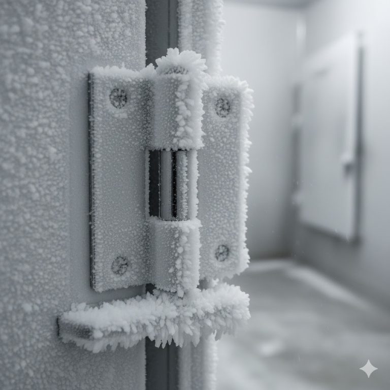
Material and finish should be selected after this architecture is stable. Outdoor, coastal, chemical, washdown, and low-temperature conditions can change the material and surface-treatment requirement, but they do not remove the need to solve the pivot, clearance, removal, and load-path geometry first.
Verify the Architecture on the Enclosure Prototype
A prototype review should confirm the complete mechanism before production tooling or large-volume ordering. Inspect the hinge in the actual door and frame, with the gasket, latches, internal equipment, cables, fasteners, and adjacent-clearance limits represented.
- Close the door without using the latch to force alignment. Check the hinge-side gap, frame contact, and free movement.
- Move the door through the full opening path. Inspect the first opening degrees, intermediate positions, and the final stop.
- Check the external and internal envelopes. Confirm clearance to nearby cabinets, walls, controls, wiring, rails, and fasteners.
- Verify the removal procedure. For removable doors, confirm the required angle, lift direction, handling method, and connected hardware.
- Inspect the load path. Look for door twist, local sheet deformation, bracket movement, loose fasteners, weld distortion, and frame deflection.
- Check gasket and latch coordination. Confirm repeatable closing position and that the hinge does not damage or roll the gasket.
- Repeat after representative operation. Recheck alignment, free play, fastener retention, door sag, and removal behavior under the project-defined validation condition.
FAQ
Should an electrical enclosure use external or concealed hinges?
Use an external hinge when the design needs a direct load path, easy mounting access, simple inspection, or minimal use of internal cabinet space. Use a concealed hinge when the exterior must remain clean and low-profile and the enclosure has enough internal clearance for the hinge body, door return, and opening path. The final choice must be checked against the actual door and frame section.
When should an electrical enclosure door use removable hinges?
Use a removable or lift-off architecture when taking the complete door away materially improves wiring, equipment installation, coating, transport, or service access. Confirm the lift direction, removal angle, overhead clearance, door-handling method, and any cables or bonding straps before selecting it.
Does a concealed hinge automatically improve the enclosure IP rating?
No. A concealed hinge can keep external hardware away from the enclosure face, but the IP performance belongs to the complete enclosure. The door, frame, gasket, latch system, hinge alignment, cutouts, fasteners, and validation test all affect sealing.
Can hinge architecture be selected from door weight alone?
No. Door weight is only one input. The architecture also depends on the door and frame section, center of gravity, hinge spacing, pivot location, opening clearance, gasket land, latch arrangement, service-removal requirement, internal obstructions, and mounting access.
Why does pivot-axis location matter on an enclosure door?
The pivot axis controls the door sweep, edge clearance, opening angle, gasket release path, interference with adjacent cabinets, and the moment transferred into the door and frame. A hinge that fits the mounting surface may still fail the opening-envelope check if the axis is in the wrong position.
What drawings are needed to review an electrical enclosure hinge architecture?
Provide the door and frame sections, overall door dimensions, hinge-side return, gasket land, latch locations, internal equipment envelope, required opening angle, adjacent-clearance limits, mounting method, door-removal requirement, and any cable or bonding-strap routing.
The correct electrical enclosure hinge architecture is the one that lets the real door clear the frame, transfer load into the cabinet, preserve service access, coordinate with the gasket and latches, and operate within the available internal and external space.
Contact HTAN for an electrical enclosure hinge architecture review with the door and frame sections, door dimensions, required opening angle, removal requirement, gasket and latch layout, internal keep-out zones, adjacent clearance, and preferred mounting method.