






Industrial hinges, handles and latches for OEM equipment.
- +86 13720060320


Industrial Pull Handle Mounting Methods for Sheet-Metal Panels
A pull handle can match every catalog dimension and still leave the door skin moving around its feet. The holes align. The joint does not. Industrial pull handle mounting methods differ in where the fastener enters, which side needs tool access, how clamping force crosses the panel, and whether the handle can be removed after the enclosure is assembled.
That is the decision this page covers. Start with the production panel, not the front view of the handle. Identify the accessible side, the sheet and reinforcement stack, the direction of the operator’s pull, the sealing boundary, and the expected service method. Only then does “through-hole,” “threaded hole,” “threaded stud,” or “weld-on” describe a usable joint rather than a catalog option.
Working rule: choose the mounting method from the panel access and load path. A clean front face, one-sided installation, easy replacement, and a strong thin-sheet joint are four different requirements. One fastener arrangement rarely delivers all four without a trade-off.
Mounting Method Is Not Handle Architecture
A fixed raised handle, recessed pull and folding handle describe what the operator sees and how the grip occupies space. They do not fully describe how the part joins the panel. A fixed handle can have clearance holes, internally threaded feet, integral studs or weldable pads. A folding base can use front bolts or rear nuts. A recessed housing may be retained by clips, studs, screws or a welded flange.
Keep those two decisions in order. First choose the grip architecture from motion, hand clearance and machine-envelope requirements. If that decision is still open, resolve it before choosing the fastener arrangement. This page begins after the architecture is known and asks a narrower question: what joint will transfer the operator’s force into the production panel?
This separation also prevents a common specification error. “Recessed” is not a sufficient mounting callout, and neither is “surface mount.” Both describe where the handle body sits relative to the panel. The drawing still needs to state the retention method, fastener direction, required access, hole or cutout geometry, and any backing structure.
Four Industrial Pull Handle Mounting Methods
The four general interfaces below cover most raised industrial pull handles. Recessed products add clip-in and cutout-specific arrangements, which are addressed later as a separate product boundary.
Use an unthreaded-hole handle with front fasteners when visible hardware and straightforward service are acceptable. Use a threaded-hole handle with rear screws or a threaded-stud handle with rear nuts when the exterior must stay clean and rear access remains available. Choose weld-on mounting only when the handle can remain permanent and welding, distortion control, inspection, and finish restoration are part of the fabrication process.
| Mounting interface | Fastener path | Access normally required | Main reason to use it | Question that can stop the choice |
|---|---|---|---|---|
| Unthreaded-hole handles with front fasteners | Screw or bolt passes through an unthreaded handle foot and into a nut, insert or structural receiver | Front tool access; rear access if a loose nut is used | Standard hardware, visible inspection and straightforward replacement | Can the receiver and thin panel carry the pull without local deformation? |
| Threaded-hole handles with rear screws | Screw passes through the panel from behind and engages a tapped hole in each handle foot | Rear tool access during assembly and service | Clean exterior face with no visible screw heads | Is the usable thread engagement correct without bottoming the screw? |
| Threaded-stud handles with rear nuts | Studs on the handle pass through panel holes and receive nuts from behind | Rear access for nuts unless the receiver arrangement is changed | Clean front, rapid location and controlled handle orientation | Is there room for the stud length, nut and installation tool behind the panel? |
| Weld-on handles | Handle legs or weldable pads become a permanent joint with the supporting metal | Welding, fixturing and finishing access | No removable fasteners and direct integration into a fabricated steel assembly | Can the weld and parent structure carry the load without distortion or corrosion damage? |
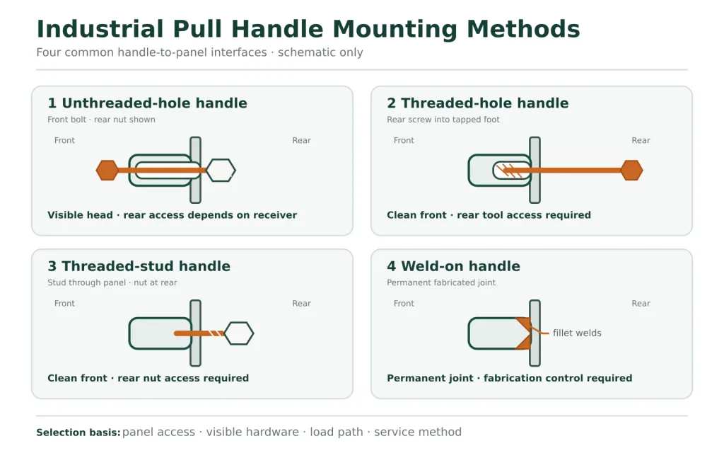
Unthreaded-Hole Handles With Front Fasteners
In this arrangement, each mounting foot has an unthreaded clearance hole. A screw or bolt enters from the visible side and passes through the handle foot and panel. The receiver may be a loose nut, a captive nut, a threaded backing plate, a self-clinching nut or another designed structural feature. The hole in the handle locates the fastener; it does not create thread engagement.
The joint is easy to inspect because the fastener heads remain visible. Replacement is usually uncomplicated when the rear nut or receiver is accessible. The trade-off is equally visible: the screw heads occupy the front face, every penetration needs an appropriate sealing detail when ingress matters, and an installer may need tools on both sides. Large clearance holes can help assembly but also allow the handle to shift before tightening. That movement should be controlled by the drawing and assembly fixture, not by an operator aligning the handle by eye.
Threaded-Hole Handles With Rear Screws
A threaded-hole pull handle contains tapped holes in its mounting feet. Screws pass from the rear of the panel into those holes, leaving the exterior face free of visible fasteners. This is useful on control panels, equipment fronts and other assemblies where the handle should be the only exterior hardware.
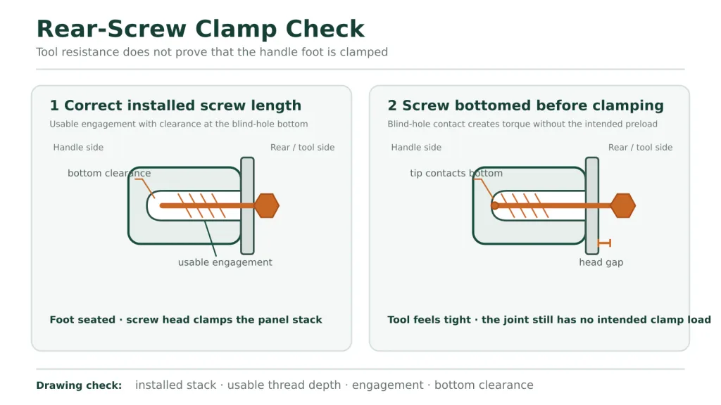
The critical dimension is not simply screw length. It is the relationship among panel stack thickness, washer or backing thickness, gasket compression, available thread depth and clearance at the bottom of the tapped hole. A screw that is too short may not develop the required engagement. One that is too long can bottom inside a blind hole before the handle foot clamps the panel. The wrench feels resistance in both cases; only one condition creates the intended joint preload.
Threaded-Stud Handles With Rear Nuts
Stud-mounted handles place the threaded projection on the handle rather than using a loose screw through the front. The studs pass through panel holes and receive nuts and any specified washers from behind. The front remains clean, and the two studs help locate the handle during assembly.
Do not confuse a clean front with blind installation. Handle-mounted studs still require access behind the panel for the nuts. If the final enclosure blocks that access, the assembly sequence must leave the rear open until the handle is secured, or the panel needs a different receiver such as captive nuts or blind threaded inserts. A stud can also be welded, swaged, pressed or otherwise retained in the handle foot. That stud-to-foot interface is part of the load path and must be included in the model-specific capacity evidence.
The dedicated comparison of through-hole and threaded-stud handles goes deeper into rear access, visible hardware and serviceability. This article keeps those two options inside the broader four-method mounting decision.
Weld-On Handles
A weld-on pull handle becomes part of the fabricated structure. The joint may be made directly at formed handle legs or through weldable pads designed for that purpose. It removes nuts and screws from the assembly and can be appropriate where the handle is permanent, rear access is unavailable after fabrication, or the surrounding structure already uses a controlled welding process.
Welding does not make the joint automatically stronger. Load still passes through the weld length, weld geometry, heat-affected parent material and the panel or frame around it. Thin sheet can distort during welding, moving the grip or pulling the mounting pads out of plane. A stainless handle welded to a different alloy or to coated steel also creates process and corrosion questions that a catalog photograph cannot answer. Weld details, material compatibility, fixturing, inspection and post-weld surface restoration belong on the production drawing or welding documentation for the project.
Panel Access Sets the First Boundary
Look at the assembled enclosure, not an empty door skin on a bench. A handle may be installed while the door is open, before internal equipment is fitted or before an inner liner closes the cavity. Service access can be very different. Wiring ducts, insulation, stiffeners, windows, latch rods and safety guards may block a socket even though the nut remains visible.
- Front access: can a driver reach each screw head without striking the grip, frame or adjacent equipment?
- Rear access: can a wrench reach the nut or screw at the installed door angle, not only on a flat panel before assembly?
- Tool path: is there room to engage the tool squarely and apply the specified tightening method?
- Future replacement: can the handle be removed without taking out equipment, drilling a weld or opening a sealed inner panel?
- Loose hardware control: could a dropped nut or washer enter an electrical, hygienic or moving-mechanism area?
One-sided installation is possible with a properly selected blind insert, captive receiver or preinstalled panel hardware, but those parts do not remove the structural question. The insert still has to resist pull-out, rotation and local sheet deformation. Its installation process and grip range must match the real panel stack. A one-sided tool path is an assembly benefit, not proof of load capacity.
The Handle Fits; the Sheet Still Moves
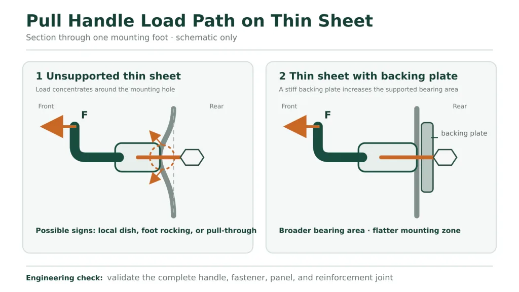
The complete load path runs from the operator’s hand through the grip, legs, mounting feet, fasteners or welds, panel skin, reinforcement and finally the door structure. A strong handle can therefore be attached to a weak joint. On a thin door, the first visible problem is often not a broken grip. The panel dimples under the feet, the holes elongate, a backing washer embeds into the coating, or the entire mounting zone flexes each time the gasket releases.
Direction changes the joint behavior. A pull normal to the panel tends to separate the feet and load the fasteners in tension or prying. A force parallel to the surface can be carried partly by friction in a properly clamped joint and partly by fastener shear after slip occurs. An angled pull combines both. If the handle is offset from the panel or the operator pulls on one end, the two mounting points may not share the load equally.
Backing plates, formed ribs, doublers, large washers and structural brackets are different ways to spread load. None is automatically required for every handle, and none should be added without checking the surrounding geometry. A backing plate can solve local bearing and create an interference with a latch rod. A formed rib can stiffen the panel and prevent one mounting foot from seating flat. The reinforcement must support the joint without disrupting the rest of the door.
Do not derive the joint load by dividing door mass between two handles. Opening force can be controlled by gasket release, hinge friction, pressure difference, rail drag, gravity and the operator’s pull direction. Carrying or lifting the complete enclosure is a separate function that requires a handle system and attachment approved for that load case.
Fastener Preload and Joint Slip
A bolted handle joint works best when the mounting feet seat firmly and the fasteners maintain enough clamp load for the intended service. Once the feet rock or the joint slips, cyclic pulling can work the holes, damage the coating and reduce preload further. A locking feature may resist fastener rotation, but it does not restore a joint that was never clamped correctly.
Too little tightening can leave gaps under a foot. Too much can dish a thin panel, crush a soft gasket, embed a washer or strip the handle’s internal thread. There is no universal torque value for “an industrial pull handle.” Fastener size and property class, thread material, lubrication, finish, washer system, insert type, panel stiffness and the supplier’s joint design all influence the correct tightening method.
The Screw Is Tight; the Foot Is Still Loose
Consider a rear-screw handle on a coated enclosure door. The hole centers are correct, and both screws reach the threaded feet. A backing layer is added later, so longer screws are selected. During assembly, each screw reaches the bottom of its blind hole before the foot fully clamps the panel stack. The tool shows resistance, yet a narrow gap remains under one foot. Repeated opening lets the handle rock, and coating dust appears around the mounting zone. Adding threadlocker would not correct the missing clamp load. The useful checks are screw under-head length, actual panel stack, available thread depth, bottoming clearance and foot seating. That failure sequence is illustrative; it is not presented as an HTAN customer case or test result.
Prevailing-torque nuts, lock washers, chemical threadlockers and mechanical retainers each have application limits. Select them for the actual vibration, temperature, cleaning chemistry and service requirement. They are secondary retention measures. Panel support, fastener engagement and clamp stability come first.
Hole Geometry and Foot Seating
Mounting center distance is only one part of the geometry. The drawing also needs hole size and tolerance, the datum used to locate both holes, panel flatness in the mounting zone, foot size, available bearing area and clearance to bends or formed features. Two individual holes can each meet a size tolerance while their combined position prevents a rigid handle from seating without force.
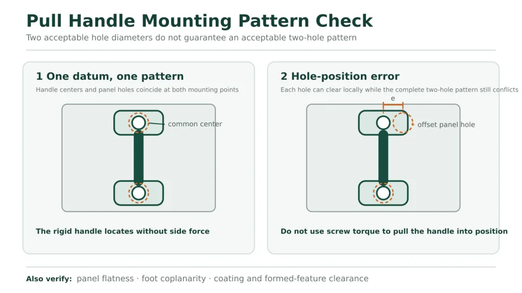
Rigid handles are particularly sensitive to noncoplanar feet. If one foot sits on a weld bead, embossment, coating buildup or local bend transition, tightening the other side can preload the handle and distort the panel. The assembly may look finished while carrying an unintended load before the operator touches it. A gasket under each foot can accommodate limited surface variation, but it should not be used to hide uncontrolled geometry.
Oversized holes are not a complete tolerance strategy. They can make assembly easier while reducing bearing area, increasing potential movement and making the final handle position dependent on the assembler. If adjustment is necessary, define the adjustment direction, finished position and washer or backing coverage. The panel shop and handle drawing must describe the same mounting coordinate system.
Sealing Is an Assembly Property
A stainless handle does not make the mounting holes watertight. Front bolts, rear screws and studs all penetrate or interface with the panel unless the design uses a continuous welded boundary. Each hole, insert, washer, gasket and mounting foot can become part of the ingress path.
For sealed enclosures, define where the seal sits and what compresses it. A gasket under a handle foot needs enough continuous contact area, compatible compression and a surface that does not cut or extrude it. A sealed washer may address the fastener head while leaving the foot perimeter unsealed. Sealant can fill a local path but may complicate removal and may not tolerate the operating environment. These details are joint-specific.
Do not claim an enclosure ingress rating from the handle alone. The rating belongs to the tested or otherwise approved enclosure assembly under its defined conditions. Changing the fastener, hole size, gasket, coating, panel thickness or tightening method can change the boundary. Record the production-intent joint in the enclosure verification plan.
Recessed pull handles need additional attention because their housing passes through a much larger cutout. Snap-in clips, flange gaskets, rear studs and weld-in housings have different retention and sealing behavior. The dedicated guide to recessed pull handle installation covers that cutout-specific task.
Vibration, Corrosion, and Service
Vibration does not act only on the nut. It exposes clearance, loss of preload, flexible panel zones and any difference in stiffness between the two mounting points. A handle may remain attached while becoming noisy or visibly loose. Inspect the joint for polished witness marks, fretting debris, coating damage, elongated holes, rotating fasteners and movement under a normal operating pull. Those signs identify where the joint is slipping.
The material system includes more than the grip. Handle feet, studs, screws, nuts, washers, inserts, weld metal, panel coating and trapped moisture all meet at the joint. Dissimilar metals can create a galvanic couple when an electrolyte is present. Crevices under feet and washers can retain cleaning fluid or salt. A corrosion-resistant handle body does not protect an unsuitable carbon-steel fastener hidden behind the panel.
Serviceability can change the preferred method even when two joints are structurally acceptable. A front-fastened joint with captive receivers may allow quick replacement. Rear screws can become inaccessible after an inner liner is installed. A damaged handle-mounted stud may require replacement of the entire handle, while a damaged panel-fixed insert may require panel repair. Weld-on mounting moves the work from fastener replacement to cutting, welding and finish restoration.
Write the intended maintenance condition into the choice: field-replaceable, factory-serviceable or permanent. Those words are more useful than “easy installation” because they identify who must reach the joint and when.
Drawing Inputs for the Mounting Joint
A purchase description such as “stainless U-handle, stud mount” is not enough to release panel holes. The handle drawing, panel drawing and assembly specification must agree on the interface. Use model-specific values; the fields below are inputs, not universal dimensions.
| Drawing input | What it controls | Required action |
|---|---|---|
| Mounting centers and tolerance | Relationship between the two handle feet and panel holes | Use one datum scheme for the complete pattern |
| Hole, stud or thread designation | Fastener fit and receiver compatibility | Match the exact handle revision and panel hardware |
| Usable thread depth | Engagement and bottoming clearance for rear screws | Separate usable engagement from total blind-hole depth |
| Stud projection | Panel stack, washer, nut engagement and tool clearance | Check the complete coated and gasketed stack |
| Foot dimensions and contact face | Bearing area, gasket land and local panel pressure | Show the true seated footprint, not only overall handle size |
| Panel thickness and material | Bearing, pull-through, crushing and insert grip range | Use production material and formed condition |
| Backing or reinforcement | Load spreading into the door structure | Locate it relative to bends, latches and internal equipment |
| Fastener and retention system | Clamp load, vibration behavior and service method | Specify the complete hardware stack and tightening basis |
| Seal or gasket detail | Ingress path and joint relaxation | Define material, position and production compression method |
| Weld callout, when applicable | Joint geometry, heat input and inspection boundary | Use the project’s controlled welding documentation |
| Access and keep-out envelope | Installation, tightening and future removal | Model the tool and hardware on the assembled door |
| Load direction and application point | How the joint is actually stressed | State the operating case instead of using “heavy duty” |
If the supplier provides a load value, request the conditions that give it meaning: direction, point of application, mounting fixture, fasteners, panel or test block, duration or cycling, and acceptance criterion. A handle tested on a thick rigid fixture does not automatically approve the same part on an unsupported door skin.
Prove the Joint on the Production-Intent Panel
A loose handle sample answers very little about mounting. Install the selected model on a representative door or panel with the intended thickness, coating, reinforcement, fasteners, washers, gasket and receiver hardware. Include nearby stiffeners, latch components and inner covers that affect tool access. The sample should reproduce the joint that production will build.
Operate the handle in the real pull direction and through the door’s normal task. Pay attention to the first breakaway event if a gasket or seal resists opening. Watch the panel around both feet rather than looking only at the grip. A door that opens can still have an unacceptable mounting joint.
| Evidence to inspect | What it may reveal | Next action |
|---|---|---|
| Gap or rocking under either foot | Noncoplanar surface, screw bottoming or insufficient preload | Measure the stack and inspect both contact faces |
| Local panel dish or oil-canning | Excess tightening or inadequate mounting-zone stiffness | Review clamp method and reinforcement |
| Hole elongation or witness marks | Joint slip, oversized clearance or repeated shear movement | Review preload, hole control and load direction |
| Nut, screw or insert rotation | Loss of retention or inadequate anti-rotation feature | Identify whether the fastener or receiver is moving |
| Gasket extrusion or uneven imprint | Incorrect compression or insufficient foot sealing land | Revise the seal detail and assembly method |
| Interference with rods, wiring or covers | Rear hardware and tool envelope were not modeled | Change receiver, location or assembly sequence |
| Corrosion or coating damage at contact points | Crevice exposure, incompatible materials or assembly damage | Review the complete material and finish stack |
| Handle movement after representative operation | Panel, fastener or foot interface is not retaining the joint | Investigate the moving interface before changing the handle body |
The required operation count, proof load, environmental exposure and allowable movement are project-specific. Define them from the equipment duty and risk. A hand pull on a bench is a fit check, not a documented capacity test. Production approval should rely on agreed acceptance conditions and evidence from the production-intent assembly.
Send the Joint Conditions With the Handle Request
For a model review, provide the handle function, pull direction, panel material and thickness, mounting-zone reinforcement, front and rear access, preferred visible-fastener condition, sealing requirement and a drawing of the available envelope. HTAN can then compare industrial pull handle mounting methods on the same assembly basis and identify which dimensions still need model-specific confirmation.
You can first review the industrial pull handle range, then submit the production panel details rather than selecting from a front-view photograph alone.
FAQ About Industrial Pull Handle Mounting
What is the difference between a threaded-hole and threaded-stud pull handle?
A threaded-hole pull handle has tapped holes in its feet, so screws normally enter from behind the panel and thread into the handle. A threaded-stud handle carries its own projecting studs, which pass through panel holes and receive nuts from behind. Both can leave a clean exterior face, but their required hardware, thread engagement, rear clearance and replacement method are different.
Do threaded-stud pull handles require access behind the panel?
Handle-mounted studs normally require rear access because nuts must be installed and tightened behind the panel. A clean front face does not mean the joint can be assembled from one side. True one-sided installation requires a suitable panel-fixed receiver, blind insert, captive feature or a different assembly sequence, and that receiver still needs structural validation in the real panel.
Which pull handle mounting method works best on thin sheet metal?
No method is automatically best for every thin panel. The joint must spread the operating load without pulling through, dishing the sheet or allowing the feet to rock. A backing plate, formed reinforcement, large bearing area or structural receiver may be needed. Choose the mounting method together with the panel support, then test the complete production-intent joint.
Is a weld-on pull handle always stronger than a bolted handle?
No. Weld-on capacity depends on the weld geometry, weld quality, parent material, heat-affected zone and the structure surrounding the joint. A controlled bolted joint on a reinforced panel may outperform a poorly supported weld on thin sheet. Compare the complete load paths and use project-specific acceptance evidence instead of assuming that the joining process proves strength.
How should pull handle mounting holes be sealed on an outdoor enclosure?
The sealing detail depends on the selected handle, fastener path, foot geometry, gasket or washer system, panel coating and enclosure requirement. Seal every actual ingress path and validate the production joint as part of the complete enclosure. A stainless handle, sealed screw or gasket by itself does not establish an enclosure ingress rating.
How much torque should be used on pull handle fasteners?
Use a joint-specific tightening requirement. The correct value depends on fastener size and property class, thread material, lubrication, finish, washers, inserts, gasket compression and panel stiffness. A universal pull-handle torque can under-clamp one joint and damage another. Obtain the model and hardware data, then validate foot seating and panel condition on the intended assembly.
Can recessed and folding handles use the same mounting methods as fixed pull handles?
Sometimes, but the handle architecture adds its own constraints. Folding handles add pivots, stops and a swept envelope. Recessed handles add a panel cutout, housing depth and flange or clip retention. They may use screws, studs or welds, but the installation drawing must also control those architecture-specific features. Do not transfer a fixed-handle mounting detail without checking the complete product structure.