






Industrial hinges, handles and latches for OEM equipment.
- +86 13720060320


How Swivel Torque Hinges Work: Structure & Rotation
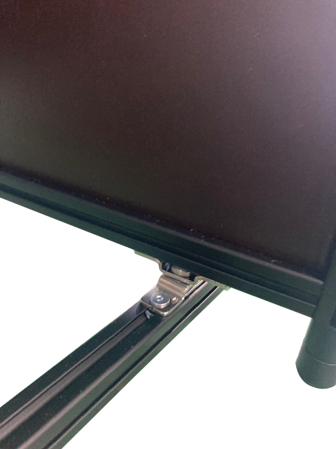
A swivel torque hinge allows a display to rotate while remaining stable at the selected angle.
A display may remain stable during an initial prototype test but later begin to drift, feel uneven, develop noise, or place excessive stress on its mounting points. These problems are not always caused by insufficient torque. They can also result from shaft misalignment, uneven preload, cable resistance, incorrect rotation architecture, or a mismatch between the hinge mechanism and the required motion.
This article explains how swivel torque hinges generate rotational resistance, how their shaft-style structure differs from a conventional leaf hinge, and how free-stop, one-way, two-way, limited-rotation, and hollow-shaft designs behave in real assemblies.
The focus is the hinge mechanism itself. Detailed load calculation, material comparison, and industry-specific selection are covered more effectively in their respective technical guides.
Demonstration of rotational resistance and angle holding.
Quick Answer: What Makes a Torque Hinge “Swivel”?
A swivel torque hinge combines a compact rotating shaft or pivot with controlled friction torque. The rotating component can be repositioned, but it does not move as freely as it would on a standard hinge. Internal friction and preload resist motion and help the attached display, bracket, panel, or cover remain stable after the operator releases it.
The word swivel describes the physical rotation arrangement rather than one universal internal design. Depending on the model, the hinge may provide limited rotation, full-circle rotation, one-way resistance, two-way resistance, a hollow center for cable routing, or movement around more than one axis.
Not every swivel torque hinge includes all of these functions. Rotation range, torque direction, cable passage, and adjustment capability must be confirmed from the product drawing or technical specification.
Swivel Torque Hinge vs. Leaf-Style Torque Hinge
Both designs can generate holding torque, but their mechanical layouts and installation requirements are different.
| Design | Main structure | Typical motion | Important consideration |
|---|---|---|---|
| Standard hinge | Two leaves connected by a pin | Free rotation | Usually cannot hold intermediate positions |
| Leaf-style torque hinge | Hinge leaves with an integrated friction mechanism | Controlled opening and closing | Requires space for the leaves and mounting fasteners |
| Swivel torque hinge | Compact shaft, barrel, hub, or rotary joint | Controlled rotation around a concentrated axis | Shaft alignment and mounting rigidity are critical |
| Detent hinge | Indexed or stepped positioning structure | Stops at preset angles | Does not necessarily hold at every angle |
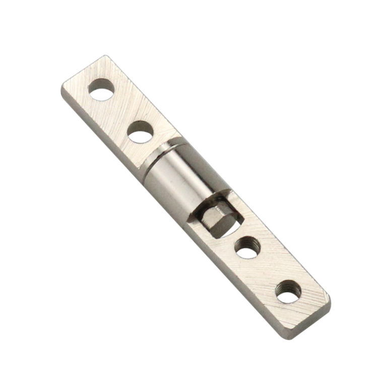
A swivel arrangement is useful when the rotating joint must fit inside a compact bracket, monitor mount, equipment head, or display support. It may also simplify the visual design by concentrating the motion around a shaft rather than using two exposed hinge leaves.
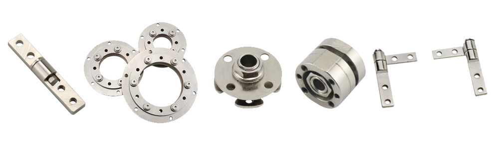
A free-stop swivel torque hinge resists rotation across its specified working range.
The Main Structural Elements
Internal construction varies by product. Swivel torque hinges should not be assumed to contain the same bearings, springs, washers, or friction materials. However, most designs include several functional elements.
Rotating Shaft or Pivot
The shaft establishes the rotation axis and transfers movement between the fixed and rotating parts of the assembly. Its diameter, support length, fit, surface condition, and alignment influence operating feel and long-term stability.
Housing or Mounting Body
The housing supports the shaft and provides the interface for mounting the hinge to the equipment. Some products use a compact cylindrical housing, while others integrate brackets, flanges, threaded sections, or mounting plates.
Friction Interfaces
Controlled friction may be generated between washers, discs, bushings, shaft surfaces, sleeves, or other internal contact areas. The exact arrangement depends on the product design and is often proprietary.
Preload Components
Springs, compressed washers, interference fits, threaded elements, or other preload structures maintain pressure at the friction interfaces. This pressure is one of the main factors that determines the resulting torque.
Stops, Detents, or Directional Elements
Some designs include mechanical stops, indexed positions, directional friction structures, or one-way elements. These features change how the hinge behaves during opening, closing, or full rotation.
.png)
The actual internal stack and friction structure should be confirmed for the specific hinge model.
How Friction and Preload Generate Torque
When the attached component rotates, the internal contact surfaces move against each other. Friction resists that movement. The contact pressure created by the preload structure determines how strongly the surfaces resist rotation.
Increasing preload will usually increase torque, but it can also increase operating force, surface stress, heat generation, and wear. Reducing preload may improve ease of movement but can allow the display or panel to drift.
The required balance is therefore not simply “more torque is better.” A successful mechanism must provide enough holding resistance while still allowing the intended user to reposition the component smoothly.
A Torque Hinge Is Not Automatically a Speed Damper
A friction torque hinge resists movement, but it does not necessarily control closing speed in the same way as a hydraulic damper or soft-close mechanism. It may help reduce uncontrolled movement when correctly matched to the load, but it should not be described as a soft-close device unless the product includes a separate speed-control mechanism.
Holding Torque, Breakaway Torque, and Running Torque
A single torque value does not always describe how a hinge feels throughout its motion. Engineers may need to consider several different behaviors.
| Term | What it describes | Why it matters |
|---|---|---|
| Holding torque | Resistance that helps the component remain at rest | Determines whether the panel drifts after release |
| Breakaway torque | Force required to start movement from rest | Excessive breakaway torque can make adjustment feel abrupt |
| Running torque | Resistance while the hinge is already moving | Affects smoothness and operating effort |
| Torque variation | Change in resistance across the rotation range | Large variation can create uneven movement |
| Torque decay | Reduction in resistance after repeated cycling | Can lead to long-term angle drift |
A hinge may have enough static holding torque but still feel poor if the initial breakaway force is too high or if the running torque changes significantly through the working angle.
One-Way vs. Two-Way Rotation Resistance
Torque direction is separate from whether the hinge is fixed or adjustable.
One-Way Torque
A one-way design provides greater resistance in one rotation direction and lower resistance in the opposite direction. This can be useful when the assembly should move easily during opening but resist movement during closing, or vice versa.
The direction must be checked before installation. Reversing the hinge or mounting it on the opposite side may change the intended operating behavior.
Two-Way Torque
A two-way design generates resistance during both clockwise and counterclockwise rotation. The resistance may be approximately balanced, or the two directions may have different specified values.
Two-way resistance is commonly used where the user must reposition a display or control interface in either direction without relying on a separate locking mechanism.
Free-Stop, Detent, and Limited-Rotation Behavior
These terms describe positioning behavior and should not be used interchangeably.
| Behavior | How it works | Main limitation |
|---|---|---|
| Free-stop | Holds at arbitrary positions within the working range | Holding performance depends on load and torque stability |
| Detent | Engages at predefined angular positions | Does not provide continuous positioning |
| Limited rotation | Mechanical stops restrict the maximum movement | Stop loads must not exceed the product design |
| Continuous rotation | Allows full or repeated rotation without a fixed angular stop | Cables and connected components may still limit rotation |
A hinge described as 360-degree does not automatically provide unlimited cable rotation. Electrical wiring, tubing, connectors, and nearby structures may impose their own movement limits.
Solid Shaft vs. Hollow Shaft
Solid Shaft
A solid shaft can provide a compact and mechanically direct rotation structure. It is appropriate when no wiring, tubing, or optical cable must pass through the axis.
Hollow Shaft
Some swivel torque hinges provide a central passage for routing cables through the rotation axis. This can reduce exposed wiring and improve the appearance of display arms, tablet stands, control interfaces, and equipment heads.
Hollow-shaft availability is model-specific. Before using the passage, verify:
- Cable outside diameter
- Minimum bend radius
- Available internal clearance
- Rotation range
- Risk of cable twisting or abrasion
- Connector size
- Required cycle life
A center hole that is large enough for a cable does not by itself guarantee reliable long-term cable movement.
Single-Axis vs. Dual-Axis Swivel Designs
A single-axis hinge controls movement around one rotation axis. It is suitable when a display, panel, or bracket only needs to tilt or rotate in one plane.
A dual-axis arrangement combines two controlled rotation axes. This can allow a monitor or interface to tilt and swivel, but the two axes must be evaluated separately. Each axis may have a different load, center-of-gravity distance, torque value, rotation range, and cable-routing condition.
Adding a second axis also increases the importance of bracket rigidity. Deflection in one bracket can be mistaken for hinge looseness or torque loss.
Common Motion Problems and Their Likely Causes
| Observed problem | Possible causes | What to inspect |
|---|---|---|
| Panel slowly drifts | Insufficient holding torque, torque decay, changing center of gravity | Load condition, hinge quantity, cycle history |
| Movement starts with a sudden jump | High breakaway torque, surface sticking, excessive preload | Initial operating force and internal friction behavior |
| Rotation feels uneven | Misalignment, mounting distortion, torque variation | Shaft coaxiality and mounting-surface flatness |
| One hinge feels tighter than the other | Uneven mounting, tolerance variation, poor load sharing | Fastener sequence, alignment and bracket rigidity |
| Noise develops during use | Contamination, wear, loosened fasteners, misalignment | Mounting points, shaft play and friction surfaces |
| Cable pulls the display away from position | Cable bending or twisting adds external torque | Cable path, bend radius and connector position |
| Torque drops after repeated use | Wear, preload relaxation, temperature or contamination | Cycle-test results and operating conditions |
What to Verify During Prototype Testing
A swivel torque hinge should be evaluated as part of the complete assembly rather than only as an isolated component.
1. Check the Full Working Angle
Move the panel through its complete intended range. Confirm that resistance remains acceptable and that no bracket, cable, fastener, or housing interferes with movement.
2. Test Angle Holding
Stop the panel at several positions, including the angle where gravity creates the greatest turning moment. Observe whether it remains stable or slowly drifts.
3. Evaluate Operating Force
The hinge must provide enough resistance to hold the component without making normal adjustment difficult. Test the assembly with the intended operator, handle position, and access direction.
4. Check Alignment and Load Sharing
When two hinges are installed on the same axis, they must remain coaxial. Misalignment can increase operating force, create noise, distort the brackets, and cause uneven wear.
5. Include the Cables
Prototype testing should use the actual cable bundle or a representative equivalent. Cable stiffness and routing can create additional torque that is not present during a hinge-only test.
6. Repeat the Test After Cycling
Compare initial movement and angle holding with performance after the required number of operating cycles. Record any change in torque, noise, play, fastener condition, or cable wear.
The required hinge torque still depends on panel mass, center-of-gravity distance, operating angle, hinge quantity, and safety margin. Use the hinge load capacity guide when calculating the required load and torque before prototype testing.
Installation and movement demonstration for a positioning hinge assembly.
When a Swivel Torque Hinge May Not Be Suitable
A swivel torque hinge is not the correct solution for every rotating assembly. Another support or motion-control system may be more appropriate when:
- The moving component is too heavy for a compact friction joint.
- The application requires controlled closing speed rather than holding resistance.
- The panel must lock positively for transport, service, or safety.
- Shock or impact loads are significantly higher than normal operating loads.
- The center of gravity changes substantially during use.
- The operating temperature exceeds the validated range of the internal friction structure.
- The assembly requires unlimited electrical rotation through the shaft.
- Mounting surfaces cannot maintain sufficient rigidity or shaft alignment.
In these conditions, the assembly may require a gas spring, mechanical stay, locking pin, detent system, rotary damper, slip ring, or a larger bearing-supported pivot combined with a separate torque device.
FAQ
What is the difference between a swivel torque hinge and a standard torque hinge?
Both provide rotational resistance. A swivel torque hinge generally uses a compact shaft, hub, barrel, or rotary-joint structure, while a conventional torque hinge often uses visible hinge leaves connected around a pivot.
Can every swivel torque hinge stop at any angle?
No. Free-stop models can hold at arbitrary positions within their working range. Detent models hold at preset angles, while limited-rotation models may only move within a defined angular range.
Can cables pass through a swivel torque hinge?
Only some hollow-shaft models provide a center passage. Cable diameter, bend radius, connector size, rotation range, abrasion risk, and required cycle life must be checked before use.
Why does a swivel torque hinge feel uneven after installation?
Common causes include shaft misalignment, distorted mounting surfaces, uneven fastener tightening, bracket deflection, cable resistance, or unequal load sharing between multiple hinges.
Conclusion
A swivel torque hinge is more than a standard pivot with extra resistance. Its performance depends on how the shaft, housing, friction interfaces, preload structure, mounting surfaces, and connected cables work together.
The most important questions are not only whether the hinge provides enough torque, but also whether its breakaway force, running resistance, rotation direction, positioning behavior, alignment, and torque stability match the complete assembly.
When requesting a swivel torque hinge, provide the equipment drawing, rotation range, load condition, hinge quantity, required resistance direction, shaft dimensions, cable-routing needs, and expected operating cycles. This allows the hinge mechanism to be evaluated against the actual movement rather than selected from a general torque value alone.
For swivel torque hinge models or a custom shaft-style rotation solution, review our swivel torque hinge range or submit your application requirements.