HTAN is one of the leading manufacturers of industrial hinges, handles and latches in China.


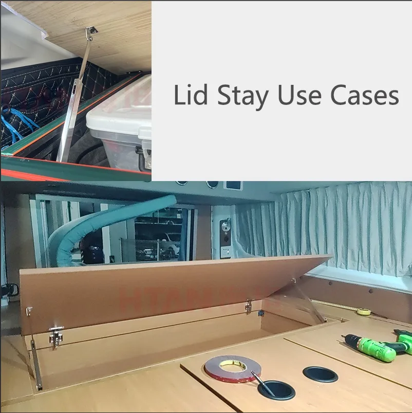
A lid stay should be selected by the behavior required from the complete lid assembly, not by a product name alone. An equipment cover may need to remain at any working angle, stop at one repeatable service position, receive opening assistance, close without dropping, fit inside a restricted cabinet, or combine several of these requirements.
The terminology can be confusing because different names describe different selection dimensions. Free-stop and fixed-angle describe where the lid is held. Friction, spring assistance, and damping describe how motion is resisted or assisted. Telescopic and two-fold describe the architecture and installation envelope. These terms should not be treated as one flat list of interchangeable lid stay types.
This pillar guide provides the selection map. It helps OEM engineers define the required behavior, identify the correct comparison page, collect the geometry needed for sizing, and verify the installed assembly without relying on unsupported service-life or load claims.
Quick Lid Stay Selection Map
| Selection Axis | Main Options | Decision Question |
|---|---|---|
| Holding behavior | Free-stop, fixed-angle, or multiple defined positions | Must the lid remain at any useful angle, or return to one repeatable service position? |
| Motion control | Friction, spring assistance, damping, or a combined mechanism | Does the lid only need to hold, or must the mechanism also reduce opening effort or control closing speed? |
| Architecture | Telescopic, two-fold, linked, or another project-specific arrangement | Is the priority long operating travel, compact folded space, or a specific mounting path? |
| Sizing geometry | Lid mass, center of gravity, hinge axis, opening range, and mounting points | What torque and travel must the installed mechanism manage throughout the motion? |
| Safety and verification | Single stay, dual stays, secondary support, or project-specific retention | What happens if the stay loses support, and what must the prototype prove before approval? |
Important distinction: one lid stay can belong to several categories at the same time. For example, a product may provide free-stop behavior through friction, include spring assistance, and use a two-fold architecture. Select each axis separately.
Start With the Required Lid Behavior
Before comparing products, describe what the lid must do when the operator releases it. This behavioral requirement is more useful than a request such as “heavy-duty lid stay” or “hydraulic support,” because it can be checked on the prototype.
| Required Behavior | Question to Confirm | Selection Consequence |
|---|---|---|
| Remain at any working angle | What portion of the opening range must be stable without hand support? | Investigate free-stop behavior and verify creep at several angles. |
| Stop at one repeatable angle | Is the service angle fixed by access, tooling, guarding, or adjacent equipment? | Investigate fixed-angle or detent-style positioning. |
| Reduce opening effort | How much operator assistance is needed, and at which part of the travel? | Consider spring assistance or another force-balancing mechanism. |
| Prevent sudden closing | Must the lid descend slowly, or only avoid uncontrolled drop? | Consider damping, spring-damper behavior, or secondary retention. |
| Close without excessive force | Can the operator overcome the mechanism near the closed position? | Check the full force curve, not only the open-position support. |
| Fit inside restricted space | What volume is available when the lid is fully closed? | Architecture and folded envelope may control the choice. |
| Remain safe after one component loosens | Would loss of support expose a person or damage equipment? | Consider dual support, secondary restraint, or a project-specific safety method. |
A complete requirement may combine several rows. For example, a top-opening inspection cover may need low opening effort, free-stop positioning between the closed and service angles, and controlled descent near closing. No single product label communicates all three needs.
Choose the Holding Behavior
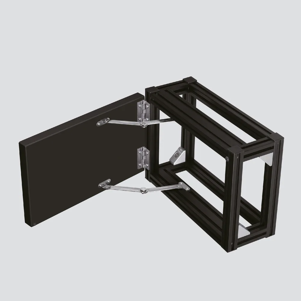
Free-stop behavior means the lid can remain at multiple positions within a defined operating range. The mechanism must provide enough resisting torque to balance the lid at those positions, while still allowing the operator to move it without excessive effort. The required behavior should be stated as a usable angular range rather than “holds anywhere,” because performance near fully closed and fully open positions may differ.
Fixed-angle behavior means the lid is intended to stop at one defined service position or at several discrete positions. This can improve repeatability where a cover must remain clear of a work area, align with a service tool, or avoid interference with nearby equipment. The stop angle, release method, tolerance, and load direction must be defined.
A free-stop requirement and a fixed-angle requirement should not be combined casually. One prioritizes flexible positioning; the other prioritizes repeatable location. The dedicated comparison of free-stop vs fixed-angle lid stays covers this decision in greater detail.
Choose the Motion-Control Method
The motion-control method determines how the lid feels during opening and closing. It should be selected separately from the holding position.
| Mechanism Function | What It Does | What It Does Not Automatically Guarantee |
|---|---|---|
| Friction | Resists relative motion and may hold the lid at multiple positions. | It does not automatically reduce the opening effort of a heavy lid. |
| Spring assistance | Provides force that can offset part of the lid’s gravitational demand. | It does not automatically control closing speed or hold every angle. |
| Damping | Controls motion speed and can reduce sudden movement. | It does not automatically support the static lid load. |
| Spring-damper combination | Can assist movement and control speed within one assembly. | Its force curve, travel, temperature behavior, and mounting geometry still require project review. |
A lid that is easy to open may still close too quickly. A lid that closes smoothly may still require the operator to hold it at the service angle. A friction mechanism may hold well but feel too heavy if the lid torque is high. The comparison of friction vs spring-damper lid stays should be used when the main decision is holding resistance versus assisted and controlled motion.
Choose the Architecture for the Available Space
The correct motion behavior is not useful if the stay cannot fit through the complete opening and closing path. Check both the open travel and the folded envelope before releasing the mounting holes.
A telescopic architecture can provide long guided travel in a relatively direct path, but it needs enough room for the extended and retracted lengths and must avoid side loading. A two-fold architecture can package into a more compact closed space, but the links, pivots, folding direction, and pinch zones must be checked throughout the motion.
The selection should be based on a swept-envelope study, not only on the nominal closed dimensions. Confirm clearance to the lid skin, frame return, gasket, hinge, latch, wiring, insulation, and service components. The detailed comparison of telescopic vs two-fold lid stays focuses on travel and folded-space tradeoffs.
Define the Inputs Before Sizing a Lid Stay
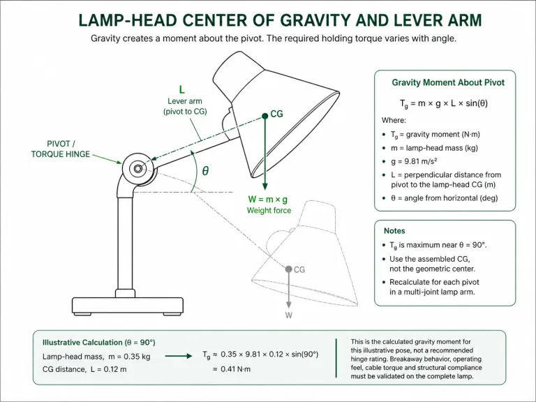
Lid mass alone is not enough for sizing. The gravitational demand changes with the center of gravity, hinge-axis location, opening angle, and mounting geometry. Two covers with the same mass can require very different support when their dimensions or hinge locations differ.
| Required Input | Why It Matters | Source |
|---|---|---|
| Complete lid mass | Defines the gravitational load of the finished assembly, including panels, windows, insulation, hardware, and attached components. | Measured prototype or controlled CAD mass properties. |
| Center of gravity | Determines the effective moment arm from the hinge axis. | CAD mass properties or physical balance measurement. |
| Hinge-axis location | Controls the rotation center and the torque demand through the opening range. | Released assembly drawing. |
| Required opening range | Defines the angles at which support, holding, damping, or release is required. | Equipment access and service requirement. |
| Closed installation envelope | Determines whether the mechanism can fold or retract without interference. | 3D packaging review. |
| Available mounting zones | Controls the stay leverage, travel, force direction, and bracket loading. | Lid and frame drawings. |
| One or two stays | Affects load sharing, torsion, synchronization, and tolerance sensitivity. | Structural and packaging decision. |
| Required release behavior | Defines whether the lid holds, descends, or closes under controlled motion when released. | Risk and usability review. |
| Operating environment | May affect friction, damping, corrosion, seals, lubricants, and material selection. | Project-specific environmental requirement. |
The dedicated guide to calculate torque for a lid stay explains the geometry and calculation path. This pillar page intentionally does not repeat the complete formula or worked example.
Check Mounting Geometry and Load Path
The stay, brackets, fasteners, lid skin, and frame form one load path. A correctly sized mechanism can still perform poorly if the bracket bends, the mounting holes move, or the lid panel twists under asymmetric support.
- Fixed and moving points: define which bracket remains on the frame and which travels with the lid, including pivot orientation.
- Closed-position interference: confirm that the stay does not contact the gasket, latch, hinge, wiring, insulation, or lid return.
- Over-center or mechanism reversal: check that the linkage does not pass into an unstable geometry unless that behavior is intentional.
- Bracket stiffness: transfer the force into a reinforced portion of the lid and frame rather than unsupported sheet.
- Fastener retention: confirm hole size, edge distance, insert or nut engagement, backing support, and access for assembly.
- Dual-stay synchronization: check tolerance, lid torsion, unequal friction, and the possibility that one side reaches its stop first.
- Pinch and trap zones: review the complete linkage path during opening, closing, installation, and maintenance.
Mounting rule: do not release the bracket holes from a catalog drawing alone. Confirm the complete lid kinematics in CAD or on an adjustable prototype fixture, then verify the real panel stiffness and fastener arrangement.
Match the Lid Stay to the Application Behavior
Application names such as “machine cover” or “electrical cabinet” are too broad to determine the mechanism. The same equipment family may contain a light inspection flap, a heavy insulated lid, a frequently opened service cover, and a guarded access panel. Match the stay to the required behavior instead.
| Application Behavior | Selection Direction | Verification Focus |
|---|---|---|
| Light inspection cover used at variable work angles | Free-stop friction stay may be a suitable starting point. | Creep, operating effort, and holding range. |
| Cover opened to one repeatable service position | Fixed-angle or defined-position stay. | Stop-angle repeatability, release method, and bracket load. |
| Heavier lid requiring reduced opening effort | Spring-assisted or spring-damper arrangement. | Force curve through the full motion and closing effort. |
| Lid that must not close abruptly | Damper, spring-damper, or project-specific secondary control. | Closing speed, temperature behavior, and end-of-travel impact. |
| Long opening travel with a direct installation path | Telescopic architecture. | Extended length, side loading, and retracted clearance. |
| Restricted closed space | Two-fold or another compact-link architecture. | Folded envelope, pivot clearance, and pinch zones. |
| Wide lid sensitive to twisting | Dual stays or a central mechanism, subject to structural review. | Load sharing, synchronization, and lid torsional stiffness. |
| High consequence if support is lost | Project-specific secondary support or redundant retention. | Single-fault behavior and the defined safety acceptance criteria. |
Verify the Installed Lid Stay
A loose component test does not prove the performance of the installed lid. Validation should use the real lid mass, center of gravity, hinge, brackets, fasteners, seals, nearby hardware, and operating environment.
| Verification Item | What to Observe |
|---|---|
| Holding position | Does the lid remain within the required angular range without unacceptable creep? |
| Opening effort | Can the intended operator move the lid smoothly without excessive force or sudden acceleration? |
| Closing behavior | Does the lid descend as intended, without uncontrolled drop or excessive closing force? |
| End-of-travel behavior | Do stops, links, brackets, and fasteners avoid impact or overload at the limits? |
| Mounting stability | Do brackets, inserts, fasteners, and panels remain aligned without permanent deformation? |
| Dual-stay operation | Do both sides move together without binding, twisting, or unequal stop contact? |
| Closed clearance | Does the folded mechanism avoid interference with the seal, latch, wiring, insulation, and enclosure contents? |
| Repeated operation | Does the behavior remain acceptable after the project-defined cycle sequence? |
Cycle count, temperature, load, speed, lubrication condition, and acceptance limits must come from the actual project or verified supplier data. Do not convert an unsupported generic cycle claim into a product approval criterion.
Lid Stay Selection Workflow
- Define what happens when the operator releases the lid (see “Start With the Required Lid Behavior”).
- Select free-stop, fixed-angle, or another defined holding behavior (see “Choose the Holding Behavior”).
- Decide whether friction, assistance, damping, or a combination is required (see “Choose the Motion-Control Method”).
- Confirm the available open travel and closed folded envelope (see “Choose the Architecture for the Available Space”).
- Collect mass, center of gravity, hinge-axis, opening-angle, and mounting-zone inputs (see “Define the Inputs Before Sizing a Lid Stay”).
- Build the mounting and bracket load path into the lid and frame structure (see “Check Mounting Geometry and Load Path”).
- Verify holding, effort, closing, clearance, and structural behavior on the installed prototype (see “Verify the Installed Lid Stay”).
Composite Engineering Scenario
This is a composite engineering scenario created to explain the selection logic. It is not a customer project record or product test claim.
An OEM is developing a top-opening service cover for industrial equipment. The initial request says only: “Provide a lid stay for a 5 kg cover.” That information is insufficient because it does not identify the center of gravity, hinge axis, operating angle, mounting zones, required holding behavior, or closing requirement.
The engineering team first defines the behavior. The cover must remain at several working angles during inspection, the operator should not need to support the full weight during opening, and the cover must not drop rapidly when released near closing. This points toward free-stop behavior combined with assistance and controlled motion rather than a simple fixed stop.
The closed cabinet has limited internal space, so the team compares the swept envelopes of a telescopic and a two-fold arrangement. A two-fold layout appears easier to package, but the links approach a wiring duct during closing. The duct position is adjusted before the bracket holes are finalized.
The team then confirms the complete lid mass and center of gravity from the finished CAD assembly, selects preliminary mounting zones, and checks bracket loads. An adjustable fixture is used to test several mounting-point combinations before the production holes are released.
The prototype review measures opening effort, holding stability at several angles, closing behavior, folded clearance, bracket movement, and left-right synchronization. The preliminary recommendation becomes acceptable only after the installed assembly meets the project-specific criteria.
FAQ
What is the difference between a lid stay and a gas spring?
A lid stay is a broader functional category used to support, hold, limit, or control a lid or cover. A gas spring is one possible force-assist device. It normally provides extension force and may include damping, but it does not automatically provide the same holding behavior, fixed-angle positioning, folded geometry, or mounting arrangement as every lid stay.
Is free-stop the same as friction?
No. Free-stop describes the required behavior: the lid can remain at multiple positions within a defined range. Friction is one mechanism that may create that behavior. A free-stop design may also combine friction with springs, dampers, links, or other elements.
Can one lid stay support any lid weight?
No. Suitability depends on the complete lid mass, center of gravity, hinge-axis position, opening range, mounting points, required holding behavior, and the force or torque capability of the specific stay. The same lid mass can create very different demand when the geometry changes.
When should two lid stays be used?
Two stays may be appropriate for a wide, flexible, or torsion-sensitive lid, or where the load must be shared across both sides. The design must account for synchronization, tolerance, unequal loading, bracket stiffness, and the risk that one side binds before the other.
Why does a lid stay creep after installation?
Possible causes include insufficient holding capacity, an incorrect mounting point, a changed center of gravity, bracket flex, fastener movement, surface contamination, wear, temperature effects, or a mismatch between the selected mechanism and the required holding behavior. Diagnose the installed geometry before replacing the stay with a higher nominal rating.
What information should I send a lid stay supplier?
Send the lid drawing, complete lid mass, center-of-gravity location, hinge-axis position, required opening range, closed-space envelope, possible mounting zones, one- or two-stay arrangement, required holding and closing behavior, access frequency, environment, and prototype acceptance criteria.
Final Lid Stay Selection
A reliable lid stay specification separates five decisions: holding behavior, motion control, architecture, sizing geometry, and installed verification. Terms such as free-stop, friction, spring-damper, telescopic, and two-fold describe different parts of the solution and should not be treated as competing labels on one list.
Define what the lid must do, collect the real mass and geometry, check the complete swept envelope, build a stable bracket load path, and verify the finished assembly. Product selection should follow those requirements. Review available industrial lid stay options after the required behavior and mounting inputs are documented.