HTAN is one of the leading manufacturers of industrial hinges, handles and latches in China.


The handle may be strong enough. The loaded toolbox can still hang badly.
A folding handle mounted at the visual center of an empty case may look correct on the drawing. Add a battery pack, power tool, tray, or dense instrument module, and the loaded center of gravity can move away from the grip axis. The case tilts as soon as it leaves the bench.
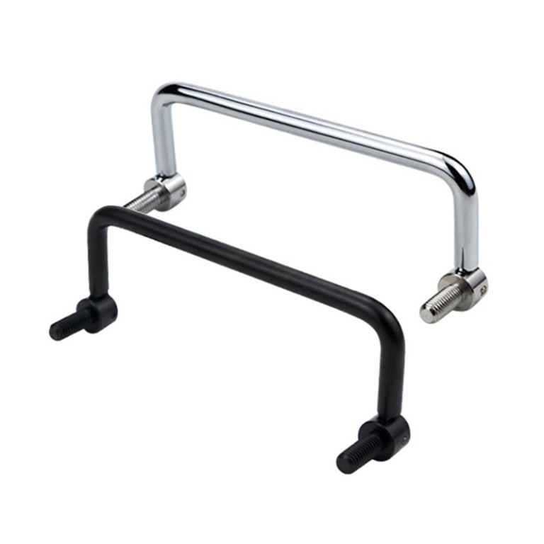
Toolbox folding handle placement should follow the loaded case, intended lifting method, panel load path, grip clearance, and stowed envelope—not the empty shell or a convenient mounting pattern.
This page begins after a folding handle has been selected as the mechanism family. The business and logistics case for using folding handles on portable equipment belongs to the industrial tool case folding handles guide. The detailed fastener, backing plate, thin-panel, and installation-strength work belongs to the heavy-duty folding handle mounting guide. The task here is narrower: locate one or two handles on the loaded toolbox, then verify carry attitude and folded clearance.
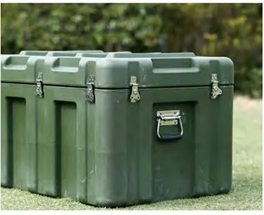
Start With the Loaded Toolbox
The empty enclosure is not the design load case. Build the placement decision around the production-intent contents and the way the case will actually be moved.
- Loaded mass: case, lid, drawers, trays, tools, batteries, cables, consumables, and removable accessories.
- Internal layout: fixed equipment, loose items, foam cutouts, compartments, and anything that may shift while the case is carried.
- Carry direction: upright, horizontal, tilted, one-handed, two-handed, or two-person.
- Access sequence: whether the handle must remain clear of the lid, latches, hinges, drawers, and service panels.
- Transport envelope: shelves, vehicle racks, pallets, adjacent cases, packaging, and storage clearances.
- Mounting structure: panel, hem, extrusion, internal frame, rib, or reinforced zone available behind the handle base.
If the production contents are not available, use a controlled mass model or equivalent ballast that reproduces the expected total weight and center-of-gravity location. A uniform block placed in the middle of the case is not representative when the actual product has dense components near one corner.
Toolbox Folding Handle Placement by Loaded Center of Gravity
Define the loaded center of gravity before choosing the grip axis. A practical symbolic model uses:
- m — loaded toolbox mass.
- Fg — gravitational force acting through the loaded center of gravity, where Fg = m × g.
- CG — loaded center of gravity.
- H — effective lifting line through the loaded grip position.
- e — perpendicular offset between the lifting line and the loaded center of gravity at pickup.
- M — initial turning moment about the lifting line.
If the loaded center of gravity is offset from the effective lifting line when the case first leaves its support, the initial turning moment is M = Fg × e. This is a general mechanics relationship, not an allowable limit. Once the case is free to rotate, it will seek an attitude in which the center of gravity lies below the lifting line. The resulting carry angle—not the initial moment alone—is what the operator must control.
Placement rule: the effective lifting line does not have to pass exactly through the loaded center of gravity, but the resulting suspended angle must remain controlled for the intended user, contents, and carry route. The acceptable relationship is project-specific and should be proven on the loaded case.
When contents can move, do not define only one nominal center of gravity. Establish a credible CG envelope that covers expected content positions during pickup, carrying, setting down, and vehicle transport. A handle location that balances the nominal arrangement may still produce an unacceptable carry angle after a battery, tray, liquid container, or loose tool shifts inside the case.
When the Empty Case Hangs Level
The empty toolbox hangs level during a design review. After the battery pack, charger, and power tool are installed, one side drops immediately when the handle is lifted. The selected handle is not undersized. Its lifting line is simply too far from the loaded center of gravity. Moving the handle, relocating the dense components, or changing to a two-handle layout may solve the problem; increasing the handle rating alone will not.
This is an illustrative engineering scenario, not a customer project record or product test claim.
Review the carry attitude in every intended orientation. A toolbox may be lifted from the top in the workshop, carried vertically through a doorway, and then loaded horizontally into a service vehicle. One handle position may not control all three states.
One Top Handle or Two Side Handles?
The layout should follow the lifting method, not a catalog preference. A centered top handle supports one-person carrying when the loaded center of gravity can remain below the grip with a controllable case attitude. Two side handles support two-handed or two-person carrying and can keep a wide case closer to level.
| Project Condition | Single Top Handle | Two Side Handles |
|---|---|---|
| Expected operator | Usually one-person carrying | Two-handed or two-person carrying |
| Loaded center of gravity | Should remain in a controllable relationship below the grip axis | Can be located between the two lifting points, but load sharing still requires validation |
| Case width | Suitable when one central grip provides stable control | Useful when a wide case twists or tilts from one central point |
| Top-surface use | Handle and base occupy the top envelope | Keeps the top available for stacking or access where the folded side profile is acceptable |
| Internal load movement | Tilt may move trays or loose tools if restraint is inadequate | Can maintain a flatter attitude when both handles are lifted together |
| Mounting structure | Top panel must transfer the full handling load into the case structure | Both side mounting zones need structural load paths into the case frame |
| Handling variation | One grip defines the carry attitude directly | One side may be lifted first or carry more load than the other |
A side-handle pair is not automatically safer or stronger. It changes the way operators control the case and creates two mounting zones that must work together.
Two Handles and Unequal Load Sharing
Two handles do not guarantee that each carries half of the load. Equal sharing is only a simplified static condition when the case is sufficiently rigid, the loaded center of gravity is correctly located between the handles, both grips are raised at the same time, and the operators maintain compatible lift heights.
In practice, one person may lift first, one side may be higher, the case may flex, or the contents may shift. The first handle can briefly carry most of the load before the second handle becomes active.
- Locate both grip axes relative to the loaded center of gravity.
- Check whether one handle can be lifted first during normal use.
- Review case torsional stiffness between the mounting zones.
- Use the same deployed grip height unless the handling method intentionally requires otherwise.
- Keep both handles clear of wheels, latches, hinges, feet, and external accessories.
- Define the worst credible handle load from the project’s lifting method and validation test rather than assuming a 50/50 split.
For a rigid case in static equilibrium, with the loaded center of gravity located between two lifting lines:
R1 = Fg × b / L
R2 = Fg × a / L
- R1 — reaction at handle 1.
- R2 — reaction at handle 2.
- a — distance from handle 1 lifting line to the loaded CG.
- b — distance from the loaded CG to handle 2 lifting line.
- L — distance between the two lifting lines, where L = a + b.
This is a preliminary static layout model. It assumes a rigid case, simultaneous lifting, fixed contents, and compatible grip heights. One-side-first pickup, case twist, moving contents, stairs, or unequal operator motion can produce a higher transient load at either handle.
Compare the project load with the supplier’s actual rating basis, not only the number printed in a catalog. Confirm whether the rating applies to one handle or a pair, the pull direction, mounting fixture, load application point, duration, allowable deformation, and whether the result is static, proof, ultimate, or cyclic. Pickup shock and one-side-first lifting still require complete-case validation.
Grip Space Around the Case
The deployed handle needs a usable hand path. A grip can be centered over the loaded case and still be difficult to use because the fingers contact the panel, a latch, the lid flange, or the handle base.
Hand Clearance
- Finger and knuckle clearance behind the grip.
- Gloved-hand access for the intended work environment.
- Enough opening to grasp without rotating the wrist into the panel.
- No pinch point between the folding arms, base, and case surface.
Nearby Hardware
- Lid latches and hinge barrels.
- Drawer pulls, feet, wheels, and corner protectors.
- Panel ribs, hems, and recessed features.
- Labels, controls, cable exits, and service openings.
Do not publish a universal grip-clearance number without a defined handle, glove type, user population, and test method. Use the actual handle sample on the production-intent case.
Load Path Into the Case Structure
The mounting location should connect the grip to the toolbox structure, not merely to a convenient flat panel. Follow the load path:
Grip → folding arms or bail → pivots and stops → mounting base → fasteners → local reinforcement → toolbox frame.
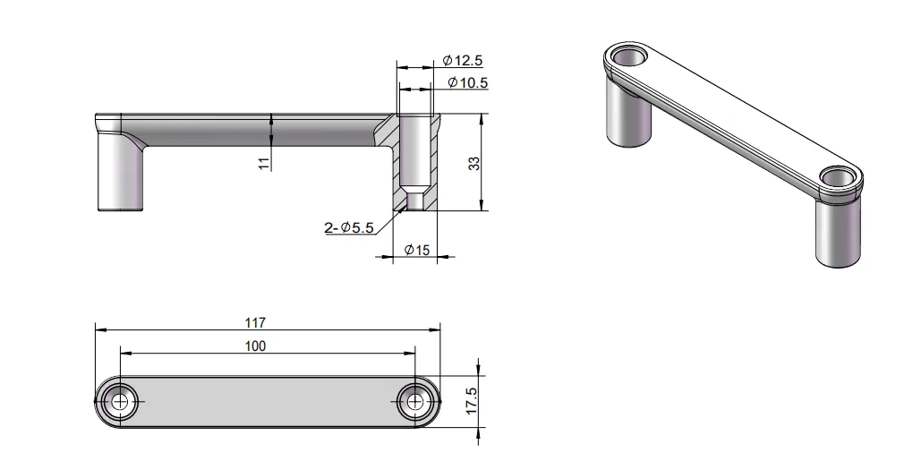
Placement questions include whether the handle base sits over a hem, rib, frame rail, extrusion, backing plate, or reinforced panel zone; whether both mounting points transfer load into the same structural region; and whether the top handle lifts the case body or only flexes the lid skin.
- A strong handle does not strengthen a weak mounting panel.
- Moving the handle closer to a structural edge can improve the load path but may reduce hand clearance or folded clearance.
- Adding reinforcement after the handle location is frozen can interfere with tools, trays, liners, or the lid.
- Two side handles need compatible structural paths on both sides of the case.
When the Handle Is Mounted on the Lid
A top handle mounted on an opening lid can place the lid panel, lid frame, latches, hinges, and lid-to-body interface inside the lifting load path. The handle may remain intact while the lid bows, a latch peels away from the case, or the hinge-side joint takes an unintended load. Before approving a lid-mounted handle, identify which components transfer the full loaded-case force into the case body and verify that the lid cannot partially open during pickup.
In a spring-return handle, the spring may control the stowed position without carrying the primary lifting load. The deployed stop, bail or folding arms, pivots, base, fasteners, and reinforced case structure must provide the intended structural path. Do not treat spring resistance or the handle’s ability to remain upright as evidence of lifting capacity.
Detailed backing-plate sizing, fastener retention, thread engagement, panel deformation, and installation torque remain with the heavy-duty mounting guide. This page only establishes where that reinforced mounting zone should be located.
Folded and Deployed Envelope
“Folding” does not mean zero projection. A surface-mounted handle may place the grip close to the case while the base, pivots, fasteners, or spring housing still occupy the transport envelope.
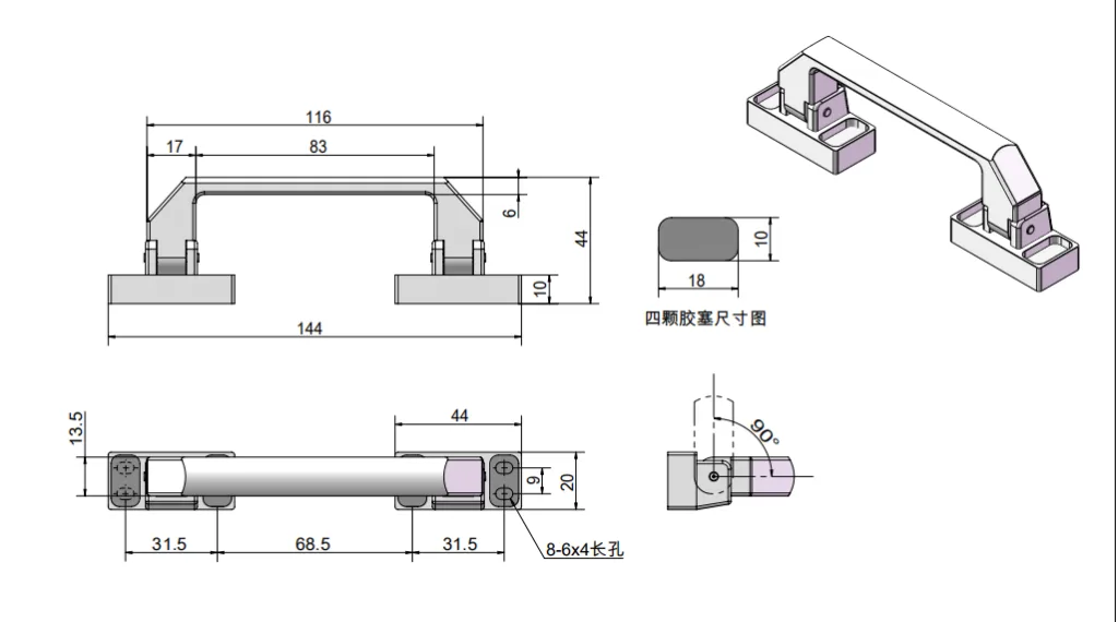
Verify whether the handle remains stowed during the project-defined movement or vibration check. A return spring can lose preload, wear, or permit rattle without visible damage to the lifting structure. Stowed retention and lifting strength are separate acceptance questions.
| Envelope State | What to Inspect | Why It Matters |
|---|---|---|
| Stowed | Base projection, grip profile, pivot housings, fastener heads, and rebound position | Determines stacking, packaging, rack, and adjacent-case clearance |
| Partially deployed | Finger entry, spring force, pinch zones, and interference with nearby hardware | Controls whether the operator can reach the full grip safely |
| Fully deployed | Grip angle, hand path, case edge, lid, latch, and wrist position | Determines usable lifting posture and whether the handle reaches a stable stop |
| Case lid opening | Handle, lid, hinge, and latch travel together | Prevents the deployed or stowed handle from blocking access |
| Transport and storage | Adjacent cases, shelf rails, vehicle restraints, corner protectors, and packaging | Confirms that the handle remains within the actual system envelope |
| Vibration or movement | Whether the handle remains stowed or rattles into the clearance zone | A moving handle can become an unexpected projection even if the static model fits |
Product browsing for surface-mounted and recessed options belongs to the folding handles category. Placement should be finalized only after the actual model’s base, pivot, deployed angle, and stowed profile are known.
Validate the Fully Loaded Case
Do not validate the handle as a loose component. Use the production-intent enclosure, internal layout, final handle, final mounting structure, latches, hinges, feet or wheels, and actual lifting method.
| Validation Check | Evidence to Record | Stop and Correct If |
|---|---|---|
| Initial lift | Direction and amount of case tilt as the load leaves the support surface | The case rotates abruptly or contents shift |
| Carry attitude | Stable angle during the intended route and operator posture | The user must continuously correct the case with the wrist or second hand |
| Single-handle-first condition | Case response when one side of a two-handle layout is lifted first | One mount, panel, or handle takes an unintended concentrated load |
| Two-handle operation | Relative case height, twist, and operator control | The case racks or one grip carries visibly more load |
| Grip access | Hand and glove clearance through deployment and lift | Knuckles contact the case or a pinch point remains |
| Mounting zone | Panel shape, fastener condition, reinforcement, and witness marks | The panel dents, cracks, loosens, or separates from the frame |
| Supplier rating basis | Rating per handle or per pair, pull direction, mounting fixture, load point, test type, duration, and allowable deformation | The catalog rating cannot be related to the installed load direction or case mounting structure |
| Dynamic pickup | Case response during the project-defined pickup, set-down, step, or handling event | Shock, one-side-first lifting, or content movement creates an unexpected handle, panel, latch, or hinge load |
| Contents and closures | Movement of tools, trays, drawers, lid, and latches | Internal mass shifts or a closure carries unintended load |
| Stowed envelope | Clearance to packaging, shelf, vehicle restraint, and adjacent cases | The base or grip remains outside the allowed envelope |
| Repeat operation | Consistent deployment, carry attitude, folding action, and retention | Position, friction, noise, or stowed retention changes unexpectedly |
The project should define the load arrangement, lifting sequence, route, repetitions, acceptance limits, and post-test inspection. A preliminary layout is not sample approval. Sample approval is not production approval unless the case, contents, reinforcement, hardware, and assembly process are controlled and repeatable.
Send the Loaded Toolbox Layout
Provide the toolbox drawing, loaded mass, nominal center of gravity and credible CG envelope, internal component layout, intended carry direction, one- or two-person lifting method, panel section, available reinforcement, supplier rating basis, grip-space requirement, and folded envelope. These inputs allow HTAN to discuss a project-specific folding-handle model and mounting location.
FAQ
Should a toolbox handle be mounted at the visual center?
Not by default. The location should be reviewed against the loaded center of gravity, intended carry orientation, case structure, grip clearance, and folded envelope. The visual center of an empty shell may not provide a stable loaded carry attitude.
Do two toolbox handles each carry half of the load?
Only in an idealized condition with a sufficiently rigid case, the center of gravity correctly located between the grips, and both handles lifted at the same height and time. Real handling can place more load on one side, so validate the worst credible lifting sequence.
Is a top handle better than two side handles?
Neither layout is universally better. A top handle may suit one-person carrying when the loaded case remains controllable below the grip. Two side handles may suit wide cases, two-person lifts, or applications that need the top surface clear, but load sharing and two mounting zones still require validation.
Does a folding handle create a zero-profile surface?
Not necessarily. Surface-mounted bases, pivots, fasteners, and spring housings can still project when the grip is folded. Use the actual model envelope when checking stacking, packaging, racks, and adjacent cases.
Can handle placement be approved using an empty toolbox?
An empty-case check can confirm basic fit and motion, but it cannot prove loaded carry attitude, load sharing, content movement, panel response, or operator control. Final validation should use the production-intent load distribution or representative ballast.
Toolbox folding handle placement is ready for release when the loaded CG envelope, effective lifting line, one- or two-handle reactions, lifting method, mounting structure, hand clearance, and folded envelope all describe the same production-intent case.