HTAN is one of the leading manufacturers of industrial hinges, handles and latches in China.


When an industrial lid stay no longer holds the cover reliably, do not begin by moving a bracket or tightening the nearest screw. First determine where the holding action is being lost: the cover may now demand more moment, the mounting geometry may no longer let the stay develop a useful reaction, the mechanism may contain lost motion, or the brackets and sheet metal may be moving under load.
Those faults can produce the same complaint—“the lid will not stay open”—but they do not require the same correction. A new stay will not stiffen a flexible mounting flange. A backing plate will not restore a worn locking slot. Moving one bracket may hide excessive clearance at one angle and create an interference problem at another.
This diagnosis applies after the required behavior is known. Some stays lock only at a defined angle, some provide friction through a stated range, and some assist or damp motion without being the sole hold-open device. If that function has not been established, use the industrial lid stay selection guide before treating normal mechanism behavior as a failure.
Before inspection, secure the cover with an independent support and control stored energy. Do not place a hand, head, or tool beneath a cover that is being held only by the suspect stay. Follow the machine isolation procedure and the instructions for the installed stay before removing a pin, loosening a bracket, or operating the cover with one stay disconnected.
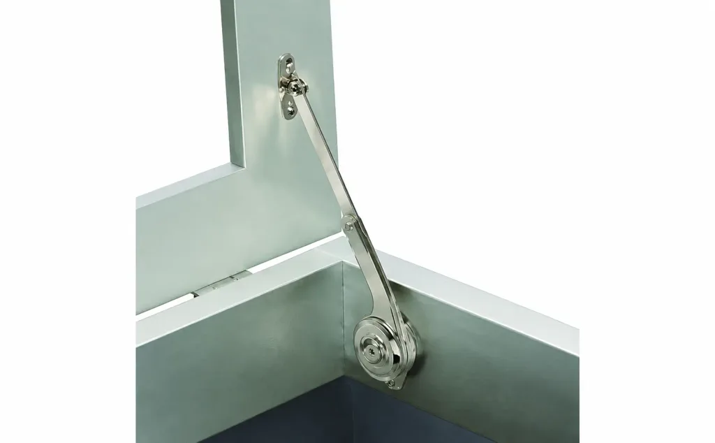
First Define the Failure You Are Seeing
“Fail to hold” is not one failure mode. Record the exact behavior before disturbing the assembly. The angle, direction of motion, and sequence in which resistance disappears are useful evidence.
- Never held after installation: start with product function, cover demand, mounting coordinates, and stop position.
- Held when new but gradually began to drift: inspect friction change, joint clearance, fastener movement, and wear at the holding feature.
- Holds only near full open: determine whether the stay reaches its designed lock point and whether the reaction angle becomes useful only late in the travel.
- Clicks or appears locked, but the cover still moves: look for motion after the lock—at pins, brackets, fasteners, panel returns, and the cover itself.
- Works on one side but not with both stays connected: inspect paired geometry, hinge alignment, cover twist, and the order in which the two mechanisms pick up load.
- Failure appeared after a cover modification: recalculate the moving assembly, including added windows, insulation, guards, handles, cables, and inner panels.
Also state what “hold” is supposed to mean. A positive-lock stay should engage its defined locking feature. A free-stop or friction stay should resist motion within its specified range. A lift-assist device may reduce opening effort without being intended to hold every angle. The pass condition must come from the selected mechanism, not from the appearance of the handle or link.
Preserve the As-Found Condition
The first inspection is most useful before adjustment. Marking bracket locations, tightening fasteners, or increasing friction can erase the evidence that separates a geometry problem from a wear problem.
- Support and isolate the cover.
- Photograph the stay at closed, first engagement, the reported failure angle, and full open.
- Mark the current fastener and bracket positions with removable witness marks.
- Record whether resistance rises smoothly, suddenly, or differently in the opening and closing directions.
- Observe the hinge, both stay brackets, the surrounding sheet, and the opposite side of the cover while load transfers.
- Note recent changes to the cover, stop, hinge, gasket, wiring, cleaning process, or operating environment.
Record Five Measurements Before Adjustment
Photographs show position, but they do not show how much motion is being lost. Record the following values from the as-found assembly so the same conditions can be compared after repair:
- Drift angle: the cover angle at which unsupported movement first begins.
- Engagement angle: the angle at first lock, detent engagement, or useful friction resistance.
- Lost input motion: handle, link, or release movement before the remote end of the stay responds.
- Bracket displacement: movement of each pivot bracket relative to a stiff frame datum while load transfers.
- Left-to-right difference: the difference in engagement angle or pickup sequence when two stays are installed.
Use the project’s existing angle and displacement instruments and record the reference points with the readings. There is no universal acceptable value for these five measurements; the purpose is to locate the changed interface and compare it with the original assembly requirement.
Do not use handle feel alone as the measurement. A stiff pivot can make a weak hold feel strong during hand operation. Conversely, a low-friction hinge can expose a marginal stay that previously appeared acceptable because hinge drag was carrying part of the cover moment.
A Lid Stay Holds Through a Complete Load Path
The holding path begins at the moving cover and ends in the enclosure structure. The visible stay is only one part of it:
cover → moving bracket → stay link and joints → fixed bracket → fasteners → enclosure panel or frame
The hinge axis, cover center of gravity, and opening stop define the external geometry around that path. A fault at any interface can reduce the moment that actually resists the cover.
| Component | What to inspect | What to observe | What it suggests |
|---|---|---|---|
| Cover and hinge | Mass distribution, center of gravity, hinge axis, hinge friction, open angle | Added components, hinge replacement, cover sag, changed stop angle | The stay is being asked to resist a different moment or at a different angle. |
| Moving bracket | Pin coordinate, bracket seating, fastener condition, local stiffness | Witness-mark movement, rocking foot, dished sheet, cracked coating | The effective mounting point moves when the cover transfers load. |
| Stay mechanism | Link straightness, stroke, friction or lock action, release reset | Uneven resistance, incomplete engagement, contamination, deformation | The mechanism is not producing or retaining its intended reaction. |
| Pins, holes, slots, and bushings | Clearance, shape, seating, retention | Free movement before output, oval holes, polished edges, debris | Input travel is being consumed as lost motion. |
| Fixed bracket and enclosure | Bracket angle, fastening, backing structure, panel stiffness | Flange rotation, fastener slip, panel oil-canning, seam movement | The reaction is deforming the support instead of holding the cover. |
| Paired stays | Side-to-side coordinates, handedness, engagement timing | One stay tight while the other remains free, cover racking | The pair is fighting twist or unequal geometry. |
| Opening stop | Stop location, stiffness, contact sequence | New contact marks, stop movement, overtravel into the stay | The stay may be carrying an unintended stop load or may not reach its lock point. |
Tracing each component, its condition, and the movement observed at that interface prevents a common mistake: replacing the stay before proving it is the failed part.
Remove the Cover Load From the Question
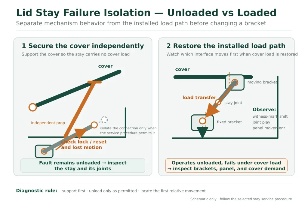
A useful first branch is whether the stay behaves incorrectly when it is not carrying the cover. With the cover independently secured—and only when the supplier’s service procedure permits it—observe the mechanism through its intended travel without using it as the cover support.
- If the lock will not engage, the release will not reset, or the motion contains obvious lost travel when unloaded, investigate the stay and its joints first.
- If the mechanism behaves consistently unloaded but the cover drifts when reconnected, continue through cover moment, mounting geometry, brackets, and panel structure.
- If the unloaded behavior changes when a bracket fastener is loosened, side load or mounting-plane misalignment may be distorting the mechanism.
This is a diagnostic separation, not an approval test. A stay that moves correctly by hand has not proved that it has sufficient holding capacity for the finished cover. It has only shown that the obvious fault may lie elsewhere in the installed load path.
Geometry Problems Depend on Angle
Cover weight creates a moment about the hinge axis. In its simplest form, that demand is cover weight multiplied by the perpendicular distance from the hinge axis to the center-of-gravity force line. Both the cover moment and the stay’s opposing moment change as the cover rotates.
This is why a lid can hold at one angle and drift at another. The stay may have adequate internal holding force, yet its line of action may pass too close to the hinge axis at the reported angle. The effective moment arm becomes small, so bracket and joint forces can rise while useful holding moment falls.
The Stay Does Not Reach Its Intended Engagement Point
A positive-lock stay may require a defined amount of travel before a slot, ratchet, detent, or telescoping feature engages. A moved bracket, a changed stop, or an altered hinge axis can leave the cover apparently open while the lock remains short of its designed position. The operator may hear contact without obtaining full engagement.
The Stay Reaches the End of Travel Too Early
If the stay becomes the hard stop before the enclosure’s intended stop contacts, impact and overtravel loads enter the stay and its brackets. A bent link, elongated hole, shifted bracket, or flexible panel can follow. Unless the manufacturer defines the installed stay as the opening stop, a holding device should not silently inherit that duty.
The Linkage Approaches an Unstable or High-Reaction Position
A folding linkage near a straight-line condition can develop high internal and bracket reactions. Moving a pivot to “make it hold harder” may therefore trade drifting for binding, release difficulty, or panel deformation. Diagnose the angle at which holding is lost; do not change coordinates based on the fully open photograph alone.
The full coordinate-development method belongs in the guide to positioning a lid stay on an industrial enclosure cover. For failure diagnosis, the key question is narrower: are the current hinge axis, A/B pivot points, and stop angle still the same relationships that were approved?
Wear Appears as Lost Motion Before It Appears as Breakage
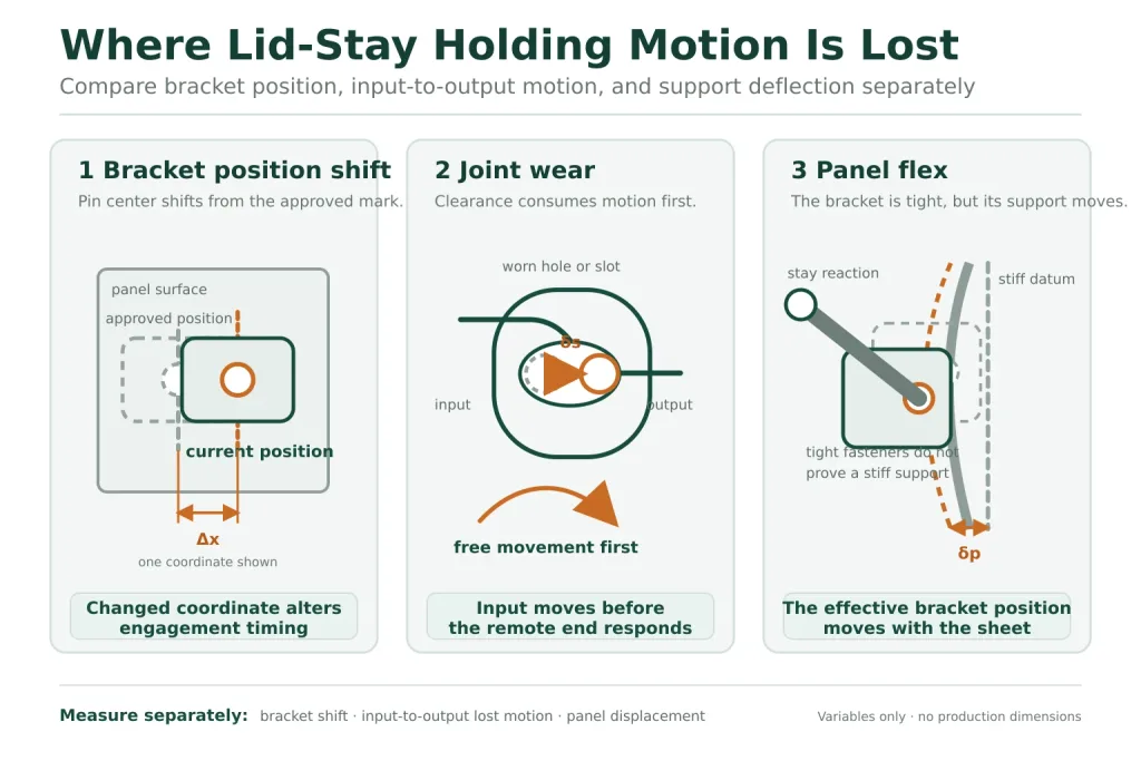
Wear does not have to produce a visibly broken arm. Small clearances can accumulate across several joints. The cover then moves while the locking or friction feature remains stationary, or the operator moves the handle before the remote end of the stay responds.
Watch one interface at a time while a controlled load is transferred. A temporary reference mark across a pin and link, or a measured reference from a bracket to a stiff enclosure datum, can reveal where motion begins. Useful evidence includes:
- oval or elongated holes;
- polished edges on slots, pins, pawls, or detents;
- fretting residue or displaced coating around a joint;
- a pin rotating in a bracket hole that was not intended to be the bearing surface;
- release travel that no longer produces immediate movement at the locking feature;
- different free play in the opening and closing directions;
- a lock that engages only when the cover is pushed beyond its normal stop.
Do not remove clearance by peening a pin, bending an arm, stacking an improvised washer, or forcing an adjustable joint beyond the supplier’s range. Those actions change alignment and can mask a worn load-bearing surface without restoring its geometry or retention.
Panel Flex Can Make a Good Stay Look Weak
A stay can lock correctly and still fail to hold the cover if its fixed or moving pivot shifts under load. Thin sheet may dish around a mounting foot. A narrow return flange may rotate. A fastener may remain tight while the hole, insert, weld nut, or backing feature moves in the panel.
Observe the bracket relative to a stiff datum, not only relative to the sheet immediately beneath it. If the bracket and nearby sheet move together, the apparent bracket position is changing even though the screws have not slipped. The effect is geometric: the stay’s pivot moves, the reaction angle changes, and some of the stay travel is consumed by elastic deflection.
A backing plate can spread load beyond a local hole, but it is not an automatic repair. The plate needs a load path into a stiff panel region or frame. Placing a large plate on a flexible unsupported bay may only move the bend line outward. Check the complete panel stack, formed returns, welds, inserts, fasteners, and adjoining structure.
Panel flex is especially easy to miss when the stay is tested on a bench fixture. A rigid fixture proves the mechanism; it does not reproduce the enclosure wall that carries the installed reaction.
Two Stays Can Fight Each Other
Adding a second stay does not simply double the support. The two sides also create a torsional system through the cover and hinge. If one stay reaches its holding feature first, it can twist the cover before the second stay picks up load. The operator experiences a cover that feels stiff, then drops or releases unevenly.
Compare left and right side evidence:
- Are both mechanisms the same model, hand, and adjustment state?
- Do corresponding fixed and moving pivot coordinates share the same hinge-axis datum?
- Do both lock, stop, or begin resisting at the same cover angle?
- Does one bracket move before the other?
- Is the cover torsionally stiff enough to distribute the load between them?
- Are the hinge segments aligned, or does the cover rack as it opens?
Never diagnose a paired system by casually removing one stay and operating an unsupported cover. If individual isolation is required, support the cover independently and follow a controlled service method.
When the Cover Changed, the Stay Did Not
A common field pattern is a stay that worked before a cover revision. The visible outer dimensions may be unchanged, yet an added inner panel, window, acoustic lining, guard, latch, handle, cable chain, or insulation layer changes the moving mass and its center of gravity. A new hinge or altered stop can change the angle at which that moment acts against the stay.
Do not compare only total weight. Two covers with the same mass can create different hinge moments when their centers of gravity are at different distances from the hinge axis. A cable or hose can also add an angle-dependent reaction that is absent when the cover is weighed separately.
If cover demand has changed, use the guide to calculate lid-stay torque and then recheck the model definition. Adjustment cannot create capacity that the mechanism and installed structure were not designed to provide.
Contamination and Friction Are Mechanism-Specific
Not every lid stay develops holding action in the same way. A friction stay depends on controlled resistance at defined surfaces. A positive-lock stay depends on complete engagement and release of a slot, pawl, ratchet, detent, or telescoping feature. A spring-assisted stay can change opening effort without providing an absolute lock.
Oil, grease, cleaner residue, dust, corrosion product, paint overspray, or washdown contamination can therefore affect models differently. Lubrication that helps a plain pivot may reduce intended friction or prevent a lock from resetting if applied to the wrong feature. Cleaning an exposed surface can also leave a dry, high-friction joint that side-loads the mechanism.
Use the maintenance sheet for the installed part number. Do not assume that a general-purpose lubricant is an appropriate repair, and do not treat temporary improvement after lubrication as proof that the underlying wear or alignment problem has been removed.
Use the Failure Pattern to Choose the Next Check
| Observed pattern | What to compare first | Likely branch | Next evidence to collect |
|---|---|---|---|
| Mechanism is inconsistent with the cover independently supported | Installed load is no longer the main variable | Lock, friction feature, pivot, contamination, or internal wear | Input-to-output motion, engagement sequence, joint clearance, part-number service sheet |
| Mechanism works unloaded but the cover drifts at every working angle | Compare cover demand with installed reaction | Capacity mismatch, changed cover, flexible support, or multiple clearances | Finished cover mass and center of gravity, bracket movement, stay definition |
| Holds at full open but not at intermediate angles | Map the angle where resistance is lost | Normal fixed-angle behavior, poor moment arm, or incomplete range definition | Required behavior, hinge axis, pivot coordinates, angle-by-angle observation |
| Lock engages, then the cover moves before the stay link moves | Trace motion after the lock | Pin clearance, bracket rocking, fastener slip, or panel flex | Witness marks and relative movement at every downstream interface |
| One stay loads before the other | Compare both sides at the same cover angle | Coordinate mismatch, unequal adjustment, hinge misalignment, or cover twist | Side-to-side pivot coordinates, engagement timing, cover and hinge alignment |
| Failure began after a cover or stop revision | Compare the previous and current moving assembly | Changed moment, center of gravity, opening angle, or stay travel | Revision drawings, added hardware, new stop contact, cable or hose reactions |
| Fasteners remain tight but a bracket changes angle under load | Reference the bracket to a stiff frame datum | Panel, flange, insert, backing, or adjoining structure deformation | Measured bracket motion and inspection of both sides of the panel stack |
The table is a routing tool, not a substitute for the supplier drawing for the installed part number. More than one fault may be present. For example, a worn pin may create lost motion while a flexible flange amplifies the resulting change in pivot location.
Correct the Changed Interface
A durable correction restores the requirement and the load path. It does not merely make the cover pass one hand test.
If Geometry Is Wrong
Return to the approved hinge axis, fixed and moving pivot coordinates, stop angle, and allowed mechanism plane. Check the full motion envelope before releasing new holes. Do not slot a bracket or lengthen a link unless that adjustment is part of the product design and remains within the supplier’s stated range.
If the Mechanism or Joints Are Worn
Replace the approved wear component or complete stay according to the model’s service policy. Inspect the mating brackets and pins before installing a new mechanism; a new stay attached to an oval bracket hole inherits the old clearance.
If the Panel or Bracket Moves
Repair damaged holes, fasteners, inserts, welds, or formed features and carry the reaction into adequate structure. A reinforcement change also changes the installed stack and fastener condition, so verify seating, clearance, corrosion compatibility, and service access as one joint.
If the Cover Demand Increased
Recalculate the finished moving assembly and reselect the stay arrangement. Do not compensate for a larger cover moment by increasing friction or adding a second stay without checking model limits, paired installation requirements, hinge capacity, bracket reactions, and cover torsional stiffness.
Prove the Repair Through the Complete Cycle
Verification should reproduce the behavior that failed. Check the cover closed, at intermediate angles, at first lock or first useful resistance, at the intended hold position, and at full open. Include the release and reset sequence, because some locking mechanisms must travel to a defined position before they can release or re-engage.
- Confirm that the installed stay performs the behavior stated on its supplier drawing.
- Confirm that the cover reaches its intended stop without using the stay as an unintended impact stop.
- Observe both bracket bases, fasteners, panel surfaces, and hinge regions while load transfers.
- Check that paired stays engage and release without twisting the cover.
- Check the folded envelope, intermediate sweep, release access, and nearby cables or hoses.
- Repeat the operating sequence sufficiently to expose intermittent engagement; do not invent a production cycle-life conclusion from a short shop check.
- Record the as-left pivot coordinates, stop angle, model, adjustment state, and corrected interfaces.
A successful repair proves the complete assembly under the project-defined conditions. It does not create a new product load rating, cycle rating, or safety certification.
FAQ About an Industrial Lid Stay Not Holding
Why does a lid stay hold only when the cover is fully open?
It may be a fixed-angle design that engages only near full open, or the installed geometry may provide a useful moment arm only late in the travel. Confirm the model’s intended behavior, then compare the actual hinge axis, pivot coordinates, lock point and stop angle with the approved drawing.
Can I tighten a lid stay that no longer holds?
Only if the exact model has a specified adjustment feature and the adjustment remains within the manufacturer’s instructions. Tightening cannot correct a shifted bracket, worn locking slot, flexible panel or increased cover moment, and excessive adjustment can raise operating effort or joint loads.
How can I tell whether the stay is worn or the panel is flexing?
Secure the cover, preserve the as-found settings and observe relative movement one interface at a time. Motion inside the stay before its output responds points toward internal lost motion. Movement of a locked bracket relative to a stiff enclosure datum points toward fasteners, the mounting stack or panel structure.
Will adding a second lid stay solve a holding problem?
Not automatically. A second stay changes bracket reactions and can twist the cover if the two mechanisms do not share matching geometry and engagement timing. Recalculate the cover demand and verify paired-model requirements, hinge alignment, mounting coordinates and cover stiffness before adding one.
Can the lid stay also be the opening stop?
Only when the selected product is specifically designed and rated for that function. Otherwise, use an independent stop so opening impact and overtravel do not enter the stay, pins, brackets or sheet-metal mounting zones.
Why does the lid stay work on a bench but fail on the enclosure?
A rigid bench fixture removes the real cover moment and may eliminate panel flex, bracket rotation, hinge misalignment and paired-stay twist. The bench test can show that the mechanism moves, but the complete enclosure test is needed to prove the installed load path.
When should an industrial lid stay be replaced instead of adjusted?
Replacement should be considered when the model’s holding or locking action remains unreliable after the installed geometry and structure are verified, or when there is deformation, damaged retention, excessive joint clearance, worn engagement surfaces or no approved service procedure for the affected part. Keep the cover independently supported until the assembly is repaired and validated.
Should I lubricate a lid stay that has become stiff or will not hold?
Use only the maintenance method specified for the exact model. Lubricant may help an approved plain pivot, but it can reduce intended friction, attract contamination or prevent a locking feature from resetting when applied in the wrong place. Temporary improvement does not prove that wear or misalignment has been corrected.
Send the Failure Evidence, Not Just a Part Photo
A useful failure review needs the exact stay model and more than one open-position image. Send the finished cover mass and center-of-gravity information, hinge-axis reference, fixed and moving pivot coordinates, required hold angle, stop position, mounting-stack details, paired-stay arrangement, and photographs of the reported motion at several angles.
Also identify whether the stay never held, lost performance gradually, or changed after a cover, hinge, stop, or maintenance revision. That evidence helps separate a model question from geometry, wear, or enclosure structure before another part is installed.
Review the available industrial lid stay product options, or send HTAN the cover drawing and as-found evidence for a model and installation review.