HTAN is one of the leading manufacturers of industrial hinges, handles and latches in China.


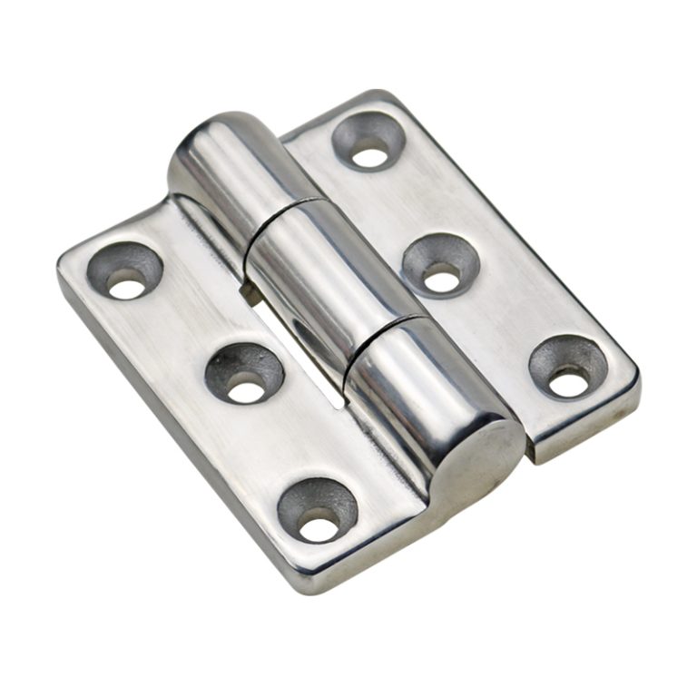
Heavy-duty stainless steel butt hinges combine a fixed-axis leaf-and-pin structure with corrosion resistance, but their suitability cannot be determined from door weight, stainless grade, or leaf thickness alone. The selection must account for the complete door mass, center-of-gravity position, hinge-axis location, vertical hinge spacing, door and frame stiffness, pin or running interface, mounting load path, and service environment.
A hinge body can remain intact while the door still sags because the mounting sheet bends, fasteners slip, welds distort the frame, or the hinge axes are not aligned. Adding another hinge also does not guarantee a proportional increase in capacity when the additional hinge cannot share load consistently.
This guide follows one selection task: confirm that a butt hinge fits the door, choose a suitable stainless grade, estimate the door moment, place the hinge set, review the leaf-pin-running structure, design the mounting joint, and validate the installed door.
Selection sequence: confirm the fixed-axis architecture → define the environment → calculate the door moment → set hinge count and spacing → review the leaf, knuckle, pin, and running interface → design the mounting load path → validate the complete door.
Confirm That a Butt Hinge Fits the Door
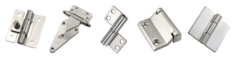
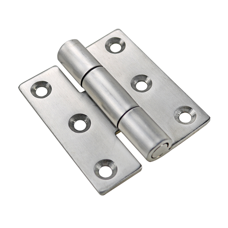
A butt hinge uses two leaves joined around a common pin axis. The leaves attach directly to the door and frame, creating a fixed swing line. This structure is appropriate when the door can rotate around one axis and both sides provide adequate mounting surfaces.
- Use a butt-hinge arrangement when the door requires a fixed swing axis, compact leaves, and a direct structural connection to the door and frame.
- Review another hinge architecture when the door must lift off without removing fasteners, translate away from a return flange, hold position through friction torque, self-close, or move through multiple axes.
- Check the closed section for leaf thickness, fastener heads, weld access, frame returns, gaskets, and knuckle clearance.
- Check the opening envelope for door sweep, pin projection, adjacent equipment, cable routing, and the required stop angle.
For a broader comparison of heavy-duty hinge families, use the heavy-duty hinge engineering guide. Continue with this page after a fixed-axis butt-hinge arrangement has been identified as suitable.
Choose 304 or 316 for the Service Environment
The term “stainless steel” does not define one corrosion performance level. Type 304 may be suitable for many indoor, humid, and controlled industrial environments. Type 316 is often a stronger starting point where chloride exposure is significant because its alloy composition generally provides better resistance to chloride-related attack. Neither grade is automatically correct for every outdoor, washdown, coastal, or chemical installation.
| Service Condition | Practical Starting Point | What Still Must Be Confirmed |
|---|---|---|
| Indoor or controlled humidity | 304 may be suitable. | Condensation, cleaning agents, finish, pin material, fasteners, and drainage. |
| Outdoor weather exposure | 304 or 316 may be considered from the actual exposure. | Chlorides, wet-dry cycles, trapped water, atmospheric contamination, and maintenance access. |
| Coastal or chloride-rich exposure | 316 is often the stronger starting point. | Salt concentration, crevices, surface finish, drainage, fasteners, and validation method. |
| Washdown service | Select from the wash chemistry rather than the word “washdown.” | Chemical type, concentration, temperature, contact time, rinse, drying, and lubricant compatibility. |
| Chemical process area | Engineering compatibility review is required. | Actual chemical, concentration, temperature, vapor or splash exposure, and all hinge-component materials. |
Request material documentation when grade matters. Appearance alone cannot confirm whether the leaves, pin, retaining parts, bushings, bearings, and fasteners use the specified materials.
Calculate Door Moment at the Hinge Line
Door weight is only the vertical load. When the door center of gravity is offset from the hinge axis, that weight creates a moment that tends to pull the upper hinge region away from the frame and push the lower hinge region in the opposite direction.
Preliminary static relations:
M = W × d
Fcouple ≈ M ÷ S
W is the complete door weight as a force, d is the horizontal distance from the hinge axis to the door center-of-gravity line, M is the resulting moment, and S is the effective vertical distance between the upper and lower hinge reaction regions. When the project provides mass m rather than weight force, use W = m × g with consistent units.
M = W × d
Fcouple ≈ M ÷ S
W is the complete door weight as a force, d is the horizontal distance from the hinge axis to the door center-of-gravity line, M is the resulting moment, and S is the effective vertical distance between the upper and lower hinge reaction regions. When the project provides mass m rather than weight force, use W = m × g with consistent units.
Two doors with the same mass can therefore require different hinge arrangements. A wider door, a door with equipment near the latch edge, or a projected hinge axis increases the center-of-gravity offset and can increase the reaction at the upper and lower mounting regions.
The force-couple estimate is an initial engineering check, not a replacement for a verified hinge rating or structural analysis. It does not include closing impact, vibration, shock, uneven frame stiffness, door flex, gasket reaction, or loads introduced by an operator.
| Door Input | Why It Matters | Required Action |
|---|---|---|
| Complete door mass | Defines the gravity load supported by the hinge set. | Include windows, latches, insulation, fans, controls, guards, and other door-mounted equipment. |
| Center-of-gravity offset d | Sets the moment about the hinge line. | Locate the CG of the equipped door rather than the bare sheet panel. |
| Effective hinge spacing S | Influences the reaction needed to resist the door moment. | Measure between the upper and lower load-transfer regions, not the overall door height. |
| Door and frame stiffness | Determines whether the reactions reach the supporting structure without local deformation. | Identify stiffeners, formed returns, backing plates, and structural frame members. |
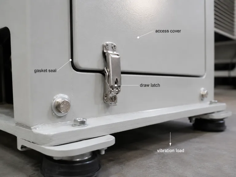
| Dynamic use | Slamming, stop impact, vibration, and shock can exceed the static condition. | Define the actual operating profile and validation exposure. |
Use the industrial hinge load-capacity guide when the project requires a broader capacity review, load direction analysis, or evaluation of supplier rating evidence.
Set Hinge Count and Vertical Spacing
Place the upper and lower hinges as far apart as the structural mounting zones allow while preserving edge distance, tool access, formed-section strength, and alignment control. Wider effective spacing can reduce the approximate reaction associated with the door moment, but only when both mounting regions are stiff enough to transfer that reaction.
Do not divide the door weight by the number of hinges and use the result as the required rating for each hinge. A multi-hinge door is a statically indeterminate assembly: small differences in hole position, weld distortion, leaf flatness, pin alignment, and frame stiffness change the actual load sharing.
| Arrangement | Useful Starting Condition | Main Risk to Verify |
|---|---|---|
| Two hinges | Rigid door and frame, adequate vertical spacing, controlled loading, and reliable mounting regions. | High reaction at the upper and lower attachments and local deformation if either region is flexible. |
| Three hinges | Tall doors, a flexible center region, frequent operation, or a need to limit local deflection. | The center hinge may carry unpredictable load or create binding if all three axes are not aligned. |
| Four or more hinges | Very tall doors, distributed structural supports, or project-specific deformation control. | Additional hinges increase alignment sensitivity and do not guarantee equal load sharing. |
- Locate hinges near structural support. Unsupported sheet may deform before the hinge reaches its own structural limit.
- Maintain one common axis. Use controlled datums, fixtures, or adjustment so the knuckles rotate without forcing the door or frame to bend.
- Support the door during installation. Do not use hinge leaves or fasteners to pull an unsupported heavy door into position.
- Recheck the latch edge. Hinge spacing, frame stiffness, and mounting deformation affect door sag and latch alignment.
Evaluate the Leaf, Knuckle, Pin, and Running Interface
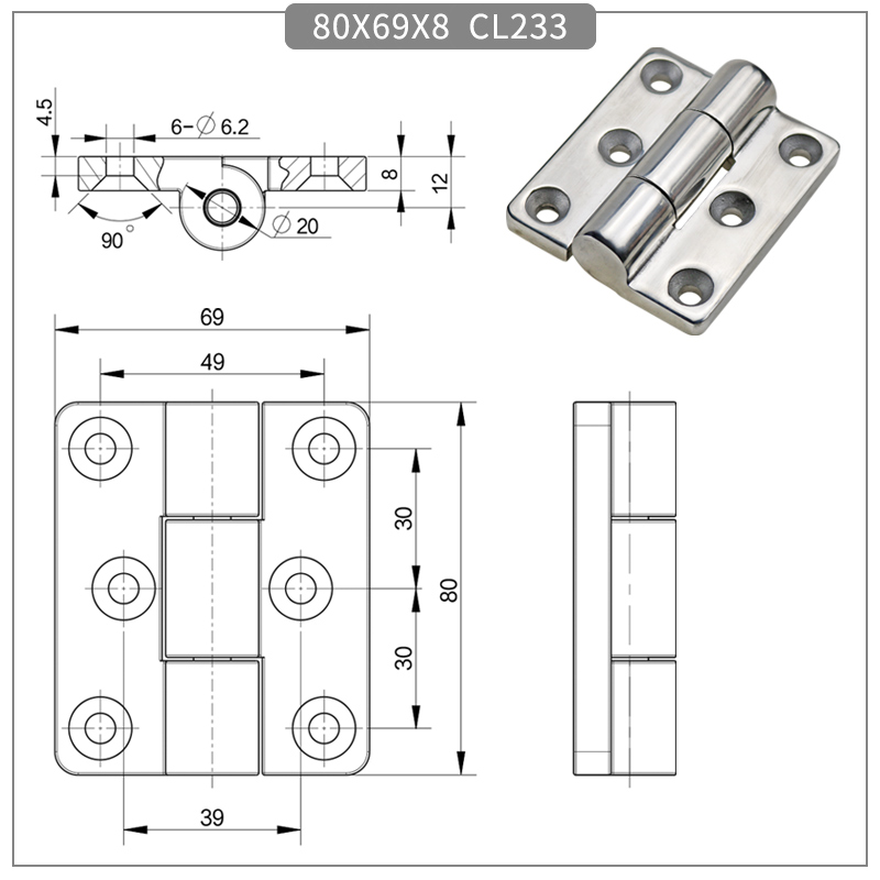
Leaf thickness is visible and easy to compare, but the load passes through the complete hinge. The leaf transfers force into the knuckles, the knuckles load the pin, the pin runs directly in the knuckle or through a bushing or bearing, and the retention feature prevents the pin or hinge assembly from separating.
| Hinge Element | Design Question | Evidence to Request or Check |
|---|---|---|
| Leaf | Can it transfer load into the fastener or weld pattern without permanent bending? | Material condition, thickness, geometry, hole pattern, edge distance, and installed contact with the support. |
| Knuckle | Does it provide enough bearing length and resist local opening, crushing, and deformation? | Knuckle length, wall section, joint geometry, forming or weld quality, and segment clearance. |
| Pin | Can it resist shear, bending, wear, corrosion, and axial movement? | Diameter, material, surface condition, support length, retention method, and permitted free movement. |
| Plain running surface | Is direct pin-to-knuckle contact suitable for the load, cycle rate, contamination, and lubrication policy? | Clearance, surface pairing, wear evidence, lubricant requirement, and allowable free play. |
| Bushing | Does it provide a suitable replaceable or lower-friction interface? | Material, fit, wall thickness, axial retention, temperature, chemical compatibility, and wear evidence. |
| Bearing | Is smoother frequent motion required, and can the bearing survive side load and contamination? | Type, sealing, static and dynamic load data, mounting fit, lubrication, misalignment tolerance, and test conditions. |
A bearing is not automatically the heavy-duty choice, and a plain pin is not automatically inadequate. The correct running interface depends on load direction, frequency, opening effort, contamination, washdown, temperature, lubrication access, misalignment, and allowable free play. Use the bushings vs. bearings guide when that interface needs a separate comparison.
Design the Butt-Hinge Mounting Load Path
The mounting structure must transfer both the vertical door load and the reaction created by the door moment. The leaf should contact a surface that can carry bearing, pull-out, peel, and local bending loads without relying on thin unsupported sheet.
| Mounting Method | Useful Conditions | Critical Checks |
|---|---|---|
| Through-bolted | Both sides are accessible and backing plates, washers, or nuts can be used. | Hole bearing, bolt preload, edge distance, backing stiffness, service access, and corrosion compatibility. |
| Threaded insert, stud, or tapped reinforcement | Rear access is limited and the attachment can be integrated into a reinforced section. | Thread engagement, pull-out, insert rotation, local support, locking method, and replacement access. |
| Machine screws into a structural member | The door or frame includes adequate thickness or a welded nut plate. | Thread strength, screw shear and tension, seating flatness, loosening risk, and alignment adjustment. |
| Welded leaf | A permanent connection is acceptable and the base material supports controlled welding. | Weld size and location, heat distortion, axis alignment, stainless cleanliness, finish repair, and replacement strategy. |
Fastener material must be reviewed as part of the joint. Stainless fasteners can reduce red-rust contamination, but thread galling, preload control, dissimilar-metal contact, tool access, and the strength of the supporting material still require attention.
Use the weld-on vs. bolt-on hinge guide when the project still needs to decide between a permanent welded connection and a removable bolted arrangement.
Control Crevices, Fasteners, and Dissimilar Metals
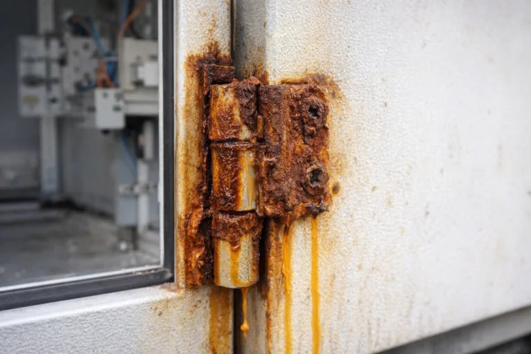
Choosing 304 or 316 does not complete the corrosion decision. The full assembly includes the leaves, pin, bushings or bearings, retaining parts, fasteners, door, frame, welds, finishes, and trapped interfaces. A stainless leaf can still be limited by an unsuitable pin, contaminated surface, damaged finish, crevice, or incompatible neighboring metal.
- Control crevices and drainage. Water, cleaning solution, salt, and debris can remain under leaves, washers, and overlapping knuckles.
- Review dissimilar-metal contact. Evaluate the hinge, door, frame, fasteners, and conductive environment as one galvanic assembly.
- Avoid carbon-steel contamination. Embedded iron from tools, grinding dust, or shared fabrication equipment can create surface rust on stainless parts.
- Protect critical surfaces. Heat tint, damaged passivation, rough crevices, or coating on a running fit can change corrosion and motion behavior.
- Define the corrosion test completely. State the method, duration, sample preparation, mounted condition, allowable corrosion, post-test operation, and reporting requirements.
A corrosion-test duration by itself does not prove suitability for every outdoor, coastal, washdown, or chemical environment.
Verify the Heavy-Duty Butt-Hinge Set on the Complete Door
Approve the hinge as an installed door system. A bench sample can confirm dimensions and basic running behavior, but it cannot reproduce the real door moment, frame flexibility, mounting deformation, latch position, gasket load, or alignment of the complete assembly.
- Confirm the parts and drawing. Verify hinge identity, material documentation where required, leaf dimensions, hole pattern, pin, bushing or bearing, and retention features.
- Support and align the door. Install the complete hinge set on representative door and frame structures without using the leaves or fasteners to force the hinge axes into line.
- Check free movement. Open through the required range and inspect binding, uneven resistance, noise, knuckle contact, pin movement, and interference.
- Measure the door position. Record latch-edge height, gaps, free play, and alignment in the closed and selected open positions.
- Inspect the mounting load path. Look for leaf bending, fastener slip, insert movement, local sheet distortion, weld cracking, frame twist, and loss of contact under the leaf.
- Apply the project-defined operating exposure. Use the specified door configuration, opening range, speed, cycle count, vibration, shock, temperature, contamination, and corrosion conditions.
- Repeat the measurements. Recheck sag, gaps, latch alignment, free play, opening behavior, pin retention, fastener or weld movement, and corrosion-sensitive interfaces.
Acceptance boundary: approve the hinge model, mounting joint, door, and frame together. A catalog load statement cannot compensate for a flexible panel, poor alignment, inadequate fasteners, or an unsupported mounting zone.
Heavy-Duty Stainless Steel Butt Hinge Selection Checklist
- Confirm that a fixed-axis butt hinge matches the door architecture and opening envelope.
- Choose 304 or 316 from the actual environment and confirm the specified grade with documentation.
- Obtain the complete door mass and center-of-gravity position.
- Calculate the preliminary door moment M = W × d using consistent units.
- Define the effective vertical spacing between the upper and lower hinge reaction regions.
- Select hinge count and position from structure and alignment rather than equal division of door weight.
- Review the leaf, knuckle, pin, retention, clearance, and plain, bushing, or bearing running interface.
- Design the fastener, insert, backing plate, structural member, or weld load path.
- Confirm pin and fastener materials, neighboring metals, finish, drainage, cleanliness, and contamination control.
- Approve the mounted hinge set after checking sag, alignment, free play, retention, and structural movement.
After the door geometry, hinge arrangement, and mounting interface are defined, review available heavy-duty hinge models against the product drawing and the project validation plan.
FAQ
Can a heavy-duty butt hinge be selected from door weight alone?
No. Door weight is only one input. Also define the center-of-gravity offset from the hinge axis, effective hinge spacing, door and frame stiffness, mounting method, opening range, operating frequency, impact or vibration, and the service environment.
Is 316 stainless steel always required for outdoor or coastal doors?
No single grade is automatically suitable for every outdoor or coastal installation. Type 316 is often a stronger starting point where chloride exposure is significant, but the final choice still depends on salt concentration, wet-dry cycling, crevices, drainage, cleaning chemicals, temperature, finish, fasteners, pin materials, and project validation.
Does adding a third hinge increase door capacity?
Not automatically. Load sharing depends on axis alignment, hole position, leaf contact, door stiffness, frame stiffness, and manufacturing tolerance. A third hinge can reduce local deflection, but it may carry little load or create binding when the three hinge axes are not aligned.
Should a heavy-duty butt hinge use a plain pin, bushing, or bearing?
Choose from the operating load, cycle frequency, required opening effort, contamination, washdown, temperature, lubrication access, misalignment, and allowable free play. A bearing is not automatically more suitable than a plain or bushed interface under every industrial condition.
What evidence should support a heavy-duty butt-hinge load rating?
The rating should identify the hinge model, hinge count, vertical spacing, door orientation, load direction, mounting substrate, fasteners or welds, fixture stiffness, static or dynamic condition, test method, acceptance criteria, and any permitted deformation or free play.
How should the installed hinge set be validated?
Install the complete hinge set on representative door and frame structures. Record alignment, opening effort, latch-edge position, door sag, free play, pin retention, fastener or weld movement, local deformation, and the same conditions again after the project-defined operating exposure.
The correct heavy-duty stainless steel butt hinge is not simply the thickest stainless model. It is the hinge set whose grade, door moment, spacing, leaf and pin structure, running interface, mounting load path, and installed evidence all match the real industrial door.