HTAN is one of the leading manufacturers of industrial hinges, handles and latches in China.


A multi-point rod lock can feel normal on the workbench and bind after the door is hung. That does not automatically mean the swing handle or center actuator is defective. The extra effort may be coming from a rod held in axial preload, a set of guides that do not share one travel line, a remote keeper applying side load, or a cabinet door that twists as it meets the frame.
The useful question is not simply, “Which part is tight?” It is, “At what state does the force enter the mechanism?” A bind that remains with the door open points toward the handle, actuator, rod joints, guides, or internal interference. A system that moves freely open but becomes heavy only as the door closes points toward the keepers, gasket reaction, hinge-supported door position, or frame geometry.
A multi-point rod lock may require increasing effort as it pulls the door into its intended gasket position. Binding is different: the effort rises abruptly, one rod branch stops before the other, a rod bows or springs sideways, or the mechanism becomes difficult only when keeper contact changes the load path.
Abnormal resistance, incomplete travel, or unequal engagement must be diagnosed on the installed assembly, where actuator travel, rod path, guide position, and keeper contact can be observed together. Panel cutout, handing, initial rod measurement, and first-article setup are covered in the swing handle and rod lock installation guide.
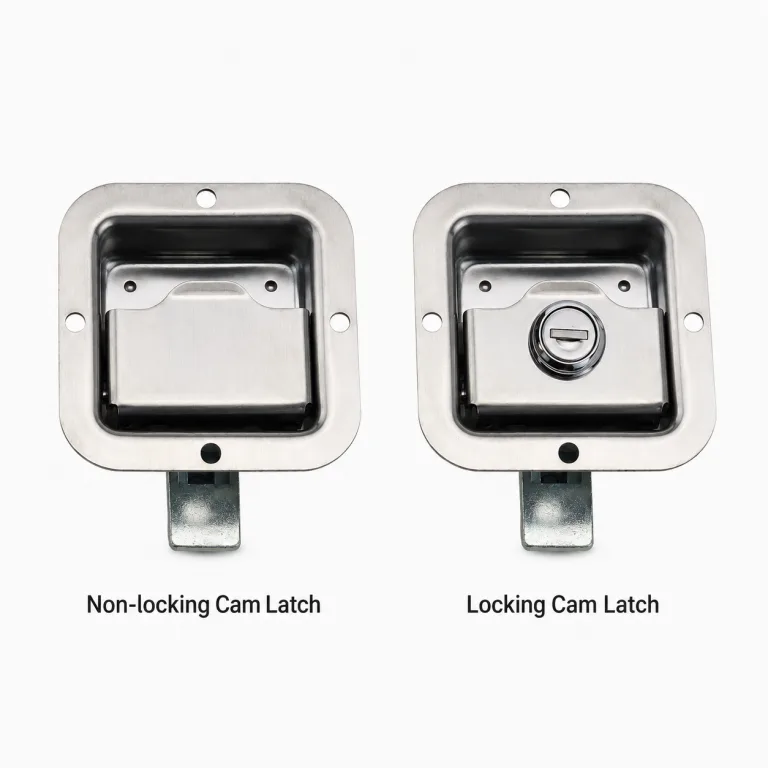
If the closure type is still undecided, compare a quarter-turn cam latch with a swing handle before diagnosing the linkage. A single-point cam latch and a rod-driven swing handle create different load paths and therefore require different troubleshooting.
First diagnostic split: if the lock binds with the door open and the remote points clear of their keepers, inspect the internal mechanism and rod path first. If it moves freely open but binds only against the frame, inspect keeper contact, door twist, gasket reaction, and hinge-supported alignment before changing rod length.
Isolate electrical equipment and follow the enclosure owner’s lockout and work-control procedure before removing covers, disconnecting linkages, or placing hands near moving rods. Do not cycle projecting rods where they can strike wiring, components, or personnel. Use the lock manufacturer’s service instructions when the mechanism includes springs, interlocks, sealed modules, or non-serviceable joints.
Name the Binding Pattern
“The lock is stiff” is not yet a diagnosis. Watch one slow operating cycle and record where the resistance begins, whether it rises smoothly or suddenly, and whether the upper and lower locking points move together. Do the same check with the door open and then in its normal closed position.
Useful observations are specific:
- The handle is heavy from the first few degrees of movement.
- The handle moves freely until one remote cam reaches its keeper.
- The upper point engages while the lower rod continues to move or bow.
- The system locks, but release requires a sudden snap or extra pull on the door.
- Resistance changes when the door is lifted, pressed at one corner, or brought gently against the gasket.
- Fresh polished marks appear on one guide edge, one side of a rod, or one keeper face.
Do not force the handle to “see whether it will go.” Forced overtravel can bend a rod, move a keeper, damage an actuator tooth, or turn a small alignment problem into several damaged interfaces. Mark the handle angle at which effort changes and photograph the positions of both remote points. Those two records are often more useful than a general statement about operating force.
Start With the Door Open
Opening the door removes the top and bottom keepers, frame contact, and most gasket reaction from the load path. The rods, guides, joints, actuator, and handle remain. That makes the open-door cycle the fastest way to separate internal drag from closing-interface load—provided the selected mechanism permits safe open-door operation.
If the same bind appears at the same handle position with the door open, look inside the door. A distorted handle housing, actuator that is already against an internal stop, rod-end joint running at an angle, guide contact, bowed rod, loose clip, or collision with a stiffener can all create that pattern. The keepers are not involved at this state.
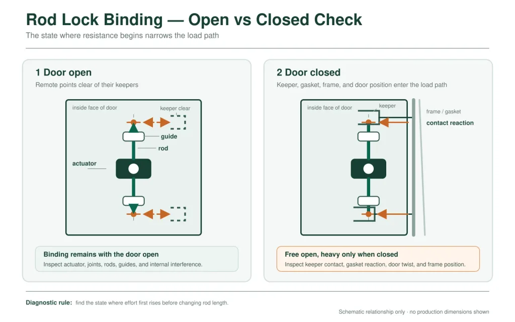
If the open-door cycle is smooth, bring the door toward the frame without operating the lock. Note whether the door reaches a repeatable rest position, whether one corner touches first, and whether the gap changes from top to bottom. Then operate the lock slowly. A force increase that begins exactly when a remote point contacts its keeper is an interface problem until evidence proves otherwise.
The drawing may fit. The closed door can still bind. Rod length is normally established from a set of datums, but the operating system only sees the assembled positions created by the hinges, door, frame, gasket, guides, and keepers. A nominally correct rod cannot remove lateral error from those parts.
Isolate the Actuator and Each Rod
When open-door operation still binds, separate the mechanism into branches. The goal is not to adjust anything yet. It is to learn whether resistance originates in the center actuator, upper linkage, lower linkage, or a combination that appears only when both rods are connected.
- Record the starting assembly. Photograph joint orientation, thread exposure, guide positions, keeper positions, clips, and the locked and released handle states. Mark adjustable joints without changing them.
- Unload the remote points. Open the door and place the mechanism in the manufacturer-defined service state. Do not disconnect a spring-loaded or trapped joint without the applicable instructions.
- Operate the center mechanism alone. If the design allows both rods to be disconnected, move the handle through its permitted travel. Continued drag points toward housing distortion, the actuator, cylinder, internal stop, or handle interface.
- Reconnect one branch. Test the upper rod, then the lower rod, using the same handle direction and observation points. A sharp change with one branch connected identifies the path that needs closer inspection.
- Watch the rod, not only the handle. Look for lateral spring-back at a joint, guide-edge contact, rod rotation, clip movement, a threaded end entering a guide, or a remote fitting reaching its limit early.
- Restore the recorded configuration. Do not leave a diagnostic disconnection, temporary loose guide, or changed thread position as the final repair.
A center actuator that runs freely by itself has passed only one isolation step. It has not proved that the actuator is correctly positioned in the door, that its output travel matches the rods, or that the complete assembly will operate under keeper load.
Rod Length Can Preload the System
A rod can connect successfully and still be the wrong effective length. The important dimension is not the cut rod by itself. It is the complete distance through the actuator connection, threaded end, joint, guide path, remote cam or roller, and keeper engagement state.
When that effective length is wrong, the linkage may carry load before the handle begins useful locking work. Depending on the mechanism direction, an overlong rod can bottom a remote point early and then bow as the actuator continues. An underset or effectively short linkage can pull a joint against its limit, reduce remote engagement, or make the opposite point carry the final travel. “Long” and “short” do not create one universal symptom because different actuators extend and retract their upper and lower outputs in different directions.
Stored Load at the Joint
With the remote point unloaded and the mechanism in its defined service position, a joint that jumps, shifts sideways, or becomes difficult to reconnect can indicate stored axial or bending preload. The observation is evidence, not an instruction to cut the rod. First rule out a guide forcing the rod off-line, a keeper holding the end fitting sideways, and a twisted door moving the installed distance.
Other rod-length clues include visible bow only near the end of handle travel, adjustment threads consumed at one extreme, one remote point reaching its mechanical stop early, unequal remaining travel at the top and bottom, or a lock that becomes free as soon as one rod-end joint is detached. Record the exact handle state for each clue.
Do not shorten a rod to compensate for a keeper that is laterally misplaced. The change may reduce handle effort while also reducing engagement or moving the problem to the opposite locking point. Correct the reference geometry first; set final rod length only after the actuator, guide line, door position, and keepers agree.
Guide Alignment Is a Line, Not a Hole
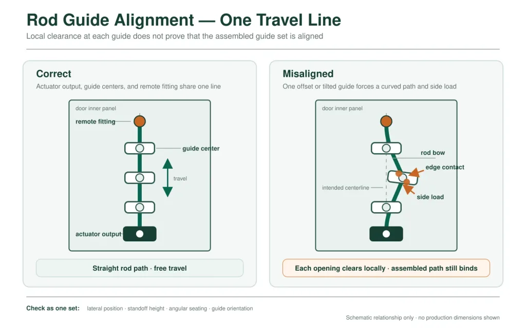
A rod can pass through every guide individually and bind after all guides are fastened. Each opening may have enough local clearance, but the guide centers may describe a shallow zigzag rather than one travel line. The assembled rod is then used as a flexible alignment tool. Friction rises, the rod stores bending energy, and the handle feels heavier than the center mechanism actually is.
Guide alignment has more than one direction. Check lateral position across the door, standoff height from the inner panel, angular seating on a stud or bracket, and orientation around the rod axis. A flat bar is especially sensitive to twist and edge contact. A round rod is more tolerant of rotation, but it can still be forced into a curved path by offset guide centers.
The installed panel adds another layer. Weld-stud angle, formed ribs, door seams, local reinforcement, mounting-bracket thickness, paint, powder coating, guide liners, and clip retention can move or tighten the working opening. A guide that slid freely on an uncoated sample may drag after finishing. A loose guide may appear to solve the problem only because its fastener now moves instead of the rod.
Look for evidence along the complete guide set:
- A polished stripe on only one edge of a rod or guide.
- Plastic dust, coating debris, scoring, or a guide liner pushed out of position.
- A rod that springs sideways when one guide is released.
- Operating effort that changes when a specific guide is temporarily loosened for diagnosis.
- A threaded joint, clip, bend, or formed feature entering the guide during part of the stroke.
- Contact that occurs in only one direction because the rod rotates or shifts under actuator load.
Do not enlarge guide openings indiscriminately. Excess clearance can trade binding for rod rattle, impact, poor remote-point location, or accelerated wear. Use the clearance, guide type, rod section, spacing, and fastening arrangement defined for the selected system; where those values are unavailable, they require supplier confirmation and representative assembly testing.
Door Twist Changes the Rod Path
The rods and guides are normally attached to the door, while the keepers are attached to the frame. Any movement between those structures changes the remote engagement geometry. Door sag moves the latch edge vertically. Panel twist changes depth from top to bottom. A racked frame moves the upper and lower keeper datums in different directions. Gasket reaction can then hold the door in a different plane from the empty-frame position used during early assembly.
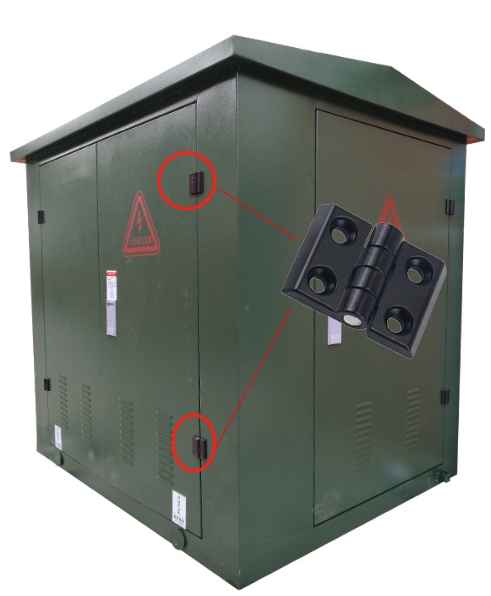
This is why a linkage may slide freely on an open door and bind only during pull-in. The actuator is now trying to do two jobs: move the rods and force the door or frame into a position that the structure does not naturally occupy. For separate guidance on hinge spacing, door support, and cabinet-door structure, use the industrial cabinet door hinge guide.
Read the door before changing the rods. Compare the unlatched gap at the top, middle, and bottom of the latch edge. Note which corner reaches the gasket first. Observe whether the door skin moves locally when the handle is turned and whether either keeper bracket deflects. If effort changes when the door is lightly supported back to its intended position, the lock is reporting a structural alignment problem.
Consider a tall door that operates smoothly while open. Against the frame, the upper roller enters first and the lower rod begins to bow. Shortening the lower rod reduces the bow, but the lower corner still sits proud and release remains abrupt. The actual cause is a twisted closed-door plane that leaves the lower keeper laterally offset. Rod adjustment changed the timing; it did not straighten the load path.
Keeper Side Load Looks Like a Rod Problem
A remote cam, roller, hook, or rod end should enter the keeper along its intended engagement path. When it contacts an edge first, the keeper applies a lateral reaction through the end fitting and back into the rod. The handle feels heavy, the rod bows, and the nearby guide may show wear. The visible rod becomes the messenger, not necessarily the cause.
Keeper side load usually appears late in the locking stroke or early during release. Look for a bright mark on one keeper edge, a roller touching only one side, a bracket that moves before the opposite point engages, or a remote fitting that becomes free as soon as the door is moved slightly away from the frame. Compare upper and lower contact at the same handle position.
Adjusting rod length may change when contact begins, but it cannot correct a lateral or depth error. Restore the door’s closed position, place the keeper on the correct engagement path, and confirm bracket stiffness before using rod-end adjustment to synchronize final travel.
The Force-Rise Point Narrows the Cause
No universal handle-force limit applies across all rod-lock models. The useful evidence is the change from the accepted baseline and the point in the stroke where that change occurs.
| Observed pattern | Load path to inspect first | Discriminating check |
|---|---|---|
| Heavy from the start, door open and closed | Handle housing, cylinder, center actuator, trapped joint, or permanent rod preload | Operate the permitted center mechanism with the rod branches isolated |
| Free at first, then drags mid-stroke with the door open | Guide offset, rod bend, rotating joint, clip, or internal interference | Watch each guide and joint while reconnecting one rod branch at a time |
| Free open; effort rises when one remote point touches closed | Keeper alignment, door twist, gasket reaction, or early end engagement | Mark the first contact point and compare the unlatched door gap |
| Upper point locks first and lower rod bows | Unequal effective rod length, guide drag, keeper mismatch, or twisted door plane | Unload the keepers, then compare each rod branch through the same actuator travel |
| Locks with normal effort but releases abruptly | Remote fitting trapped under side load or excessive pull-in | Inspect keeper witness marks and observe whether moving the door away removes the bind |
| Intermittent or direction-dependent drag | Loose guide, rod rotation, damaged liner, contamination, worn joint, or contact with internal equipment | Record the exact direction and locate fresh movement or wear evidence before cleaning or adjustment |
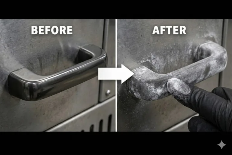
Contamination, corrosion, worn guides, bent rods, and damaged actuator parts can produce similar symptoms. If the geometry is unloaded and aligned but resistance remains, inspect those conditions against the exact model’s service limits. Use only model-approved cleaning and lubrication practices. Lubricant can reduce friction temporarily; it cannot make offset guide centers collinear or move a keeper into the correct plane.
Correct Geometry in the Right Order
Changing the easiest adjustment first is tempting. It also makes troubleshooting harder because every later observation is based on a new, undocumented configuration. Work from the structures that establish the reference positions toward the adjustable linkage.
- Restore the door and frame relationship. Correct hinge looseness, sag, panel twist, frame rack, bent keeper brackets, and abnormal gasket interference that move the closed-door plane.
- Seat the handle and actuator without distortion. The housing, rear bracket, and fasteners must hold the mechanism without twisting it in the cutout or forcing its outputs off-line.
- Establish one guide path for each rod. Align guide centers, standoff, angular seating, and rod orientation while preserving the specified running clearance.
- Place the remote keepers on that path. Correct lateral, vertical, and depth contact so the cam, roller, hook, or rod end does not enter on an edge.
- Set effective rod length and synchronization. Adjust only after the fixed geometry is stable. Preserve the required thread engagement and usable adjustment in both directions.
- Secure the released configuration. Tighten fasteners and retain joints using the model-specific method, then repeat the same isolation checks to make sure tightening did not move a guide or housing.
If inspection identifies a worn or incompatible rod, guide, end fitting, actuator, or keeper, match the replacement to the original interface and complete door geometry before selecting from the industrial latches category. A similar-looking part from another system may change travel, engagement, or guide alignment.
Retest the Complete Door
A free rod on an open door is not the final acceptance condition. Reassemble the production-intent handle, actuator, rods, guides, remote fittings, keepers, hinges, gasket, fasteners, and internal equipment. Then repeat the same slow operating sequence used to identify the fault.
- Both rod branches move freely with the door open and remain within their intended travel envelope.
- Upper and lower remote points begin engagement in the accepted sequence without rod bow or keeper deflection.
- Handle effort rises smoothly where pull-in is intended rather than spiking at an edge contact.
- The actuator reaches its intended locked and released states without forced overtravel.
- The door gap and gasket contact remain consistent with the project requirement.
- No new polished mark, coating damage, loose guide, shifted keeper, clip movement, or joint spring-back appears after the defined repeat check.
Record the exact hardware revision, thread positions, guide and keeper locations, door condition, operating state, and result. Temperature, vibration, washdown, or cycle exposure should be added only when it belongs to the real application and has project-defined conditions and acceptance criteria.
Share the Binding Pattern
Send the swing-handle or actuator model, available drawing, one slow video with the door open, one with the door closing, photos of both rod paths and keepers, the handle position where effort rises, and any visible bow or witness marks. These details make it possible to discuss whether the next review should focus on rod setup, guide alignment, keeper contact, damaged hardware, or the cabinet-door structure.
FAQ About Multi-Point Rod Lock Binding
Why is a multi-point rod lock hard to turn only when the door is closed?
If the mechanism moves freely with the door open, the added resistance is probably entering through remote keeper contact, door twist, hinge-supported door position, frame alignment, or gasket reaction. Mark where each remote point first touches and compare the unlatched door gap before changing rod length.
Can shortening a rod fix a binding three-point lock?
It can change engagement timing, but it should not be the first correction. A guide offset, laterally misplaced keeper, twisted door, or early mechanical stop can all make a rod appear too long. Correct the fixed geometry first, then set effective rod length while preserving required thread engagement and adjustment range.
How can I tell whether a rod guide is misaligned?
Typical evidence includes a polished mark on one guide edge, rod spring-back when a joint or guide is released, plastic or coating debris, direction-dependent drag, and a clear change in operating effort when one guide is isolated during a controlled diagnostic check. All guide centers must support one intended travel path.
Why does one rod-lock point engage before the other?
Possible causes include unequal effective rod lengths, different end-adjustment positions, guide friction, early keeper contact, actuator orientation, remote fitting geometry, door twist, or frame mismatch. Test each branch with the keepers unloaded, then compare the first-contact position on the closed door.
Is visible rod bow acceptable when a multi-point lock is closed?
Do not assume that it is acceptable. Bow can show that the linkage is storing length error, guide offset, keeper side load, or excessive pull-in. The permitted condition must come from the exact product drawing and project acceptance criteria; unexplained bow should be diagnosed before release.
Will lubricant stop a multi-point rod lock from binding?
Only when the exact model permits lubrication and friction—not geometry—is the verified cause. Lubricant cannot correct offset guide centers, a twisted door, early keeper contact, or the wrong effective rod length. It can also collect contamination or affect plastics and seals, so follow the model-specific service instruction.