






Industrial hinges, handles and latches for OEM equipment.
- +86 13720060320


How to Specify an In-Line Torque Hinge for Embedded Panels
An in-line torque hinge should be specified as part of the rotating shaft and housing interface, not as a separate leaf hinge added after the panel design is complete. Its cylindrical body, output shaft, anti-rotation geometry, axial retention, and surrounding structure must work together to generate controlled resistance without slipping, binding, or overloading the enclosure.
A request such as “0.5 N·m inline hinge for a flip cover” is incomplete. The engineer must define the total panel torque, opening and closing behavior, breakaway and running torque, body envelope, shaft engagement, housing bore, alignment, maximum opening angle, torque tolerance, cycle profile, and end-of-life acceptance.
This guide is limited to that integration task. For a broader comparison across fixed, adjustable, concealed, and other hinge families, use the guide to choosing a torque hinge. This page remains focused on shaft-aligned in-line architecture.
When an In-Line Torque Hinge Fits the Product
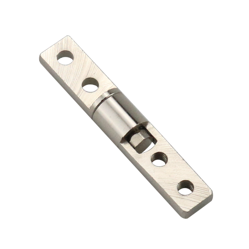
An in-line hinge places the torque mechanism close to the rotational axis. It is a practical starting architecture when the product needs a narrow pivot line, a concealed cylindrical body, or a hinge embedded in a molded, machined, or die-cast housing.
- Suitable starting conditions: embedded flip panels, compact instrument displays, control interfaces, and small equipment covers with a defined shaft axis.
- Required housing capability: enough local stiffness and engagement to react the hinge torque without bore rotation, creep, cracking, or permanent deformation.
- Required assembly control: a clear anti-rotation feature, axial-retention method, and installation direction.
- Dual-hinge condition: a common axis, controlled tolerance stack, and a plan for left-right load sharing and synchronization.
An in-line hinge is a poor choice when the surrounding structure cannot react the torque, the two pivot supports cannot remain coaxial, or the hinge would be forced to carry major radial or bending loads. Unless the model documentation explicitly allows otherwise, treat it as a motion-control component rather than the only structural bearing or shaft.
Applications such as laptops introduce additional requirements for display feel, bezel packaging, cable routing, drop behavior, and user perception. Those belong in the dedicated guide to laptop torque hinge requirements, not in this general in-line integration page.
Define the Panel Torque Before Selecting a Hinge
The required hinge torque starts with the complete rotating assembly, not the cover mass shown on an early concept drawing. Include the finished panel, display, glass, trim, fasteners, wiring, insulation, attached controls, and any components that move with the panel.
| Input | Why It Matters | Recommended Source |
|---|---|---|
| Complete panel mass | Defines the gravitational load of the finished rotating assembly. | Controlled CAD mass properties or measured prototype. |
| Center of gravity | Defines the lever arm from the hinge axis. | CAD mass properties or physical balance measurement. |
| Hinge-axis position | Controls the perpendicular distance and panel motion. | Released assembly drawing. |
| Installed orientation | Horizontal, vertical, and inclined axes create different gravitational demand. | Actual equipment installation. |
| Required angular range | Defines where the panel must move and hold. | Equipment access and usability requirement. |
| Additional resistance | Cables, seals, springs, detents, and latches may change opening and closing torque. | Complete assembly test or controlled component data. |
| Hinge quantity | Determines the preliminary torque allocation per hinge. | Architecture and structural decision. |
| Operator-force target | Controls the intended feel and whether the panel is too heavy or too stiff. | Project-specific usability requirement. |
The basic relationship is force multiplied by the perpendicular distance from the hinge axis. That relationship establishes the panel demand, but it does not by itself define the final product torque. The engineer must still decide the desired operating feel, holding margin, influence of other components, number of hinges, and acceptable difference between opening and closing.
Specification rule: state the total assembly torque and the intended torque per hinge. Do not write only “two 0.5 N·m hinges” without identifying whether 0.5 N·m applies to each hinge or to the complete panel.
Specify Torque Behavior and Measurement Conditions
Torque terminology is not fully interchangeable across supplier datasheets. One supplier may report starting torque, another breakaway torque, and another a peak measured during a defined angular movement. Compare values only after confirming the direction, speed, angular range, temperature, fixture, and measurement point.
| Torque Field | What to Define |
|---|---|
| Opening and closing torque | Running torque in each direction, including whether the design is symmetric or intentionally different. |
| Breakaway torque | Peak torque required to start movement after the defined dwell condition. |
| Running torque | Torque measured after movement begins at a defined speed and angular position. |
| Holding requirement | Positions or angular range where the panel must remain without unacceptable drift. |
| Torque direction | Clockwise, counterclockwise, opening, closing, one-way, or two-way. |
| Torque tolerance | Initial minimum and maximum per hinge and, where relevant, for the complete assembly. |
| Measurement condition | Angular range, speed, temperature, fixture, dwell time, and measurement point. |
| End-of-life torque band | Minimum and maximum acceptable torque after the specified cycle profile. |
Two hinges with the same nominal torque may behave differently if one has a higher starting peak, a wider tolerance, a different opening-to-closing ratio, or greater torque change after cycling. The measurement definition is part of the specification, not a secondary test note.
Define the Shaft and Housing Interface
The interface drawing is the core of an in-line torque hinge project. One hinge interface must react against one assembly member, while the mating interface rotates with the other member. The drawing must identify which side is fixed, which side rotates, and how torque is transferred on both sides.
| Interface Field | Drawing Requirement |
|---|---|
| D — body diameter | Maximum cylindrical envelope and tolerance that fit the housing. |
| L — body length | Overall installed length and required assembly depth. |
| d — output shaft diameter | Rotating connection size, tolerance, and mating material. |
| E — shaft engagement | Length available to transmit torque without slip or local damage. |
| B — housing bore | Bore size, tolerance, surface condition, housing material, and wall support. |
| C — installation clearance | Space for insertion, tools, adjacent walls, and tolerance stack. |
| A — axial retention | Shoulder, clip, flange, formed end, threaded feature, or another defined method. |
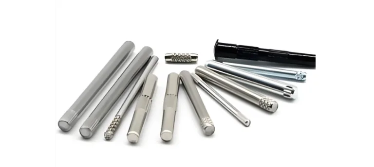
| Anti-rotation feature | Flat, spline, knurl, key, profile, pin, clamp, or another positive torque-reaction feature. |
| Datum and axis | Reference features used to control coaxial alignment. |
| Installation direction | Orientation of the body, output shaft, and required torque direction. |
| End-stop responsibility | Define whether the maximum opening angle is controlled by the hinge or by a separate structural stop. |
A press fit is not automatically an anti-rotation solution. Its suitability depends on bore tolerance, material stiffness, wall thickness, surface condition, expected torque, temperature, assembly process, and long-term creep. Plastic housings often need a mechanical flat, molded profile, insert, bracket, or other positive reaction feature.
End-stop boundary: do not use the in-line torque hinge as the primary hard stop unless the specific model is rated for the end-of-travel load. A separate structural stop may be required to prevent impact from passing through the friction mechanism, shaft, or plastic housing.
Prevent Housing Slip, Misalignment, and Stop Overload
Many in-line hinge failures originate outside the internal friction mechanism. The hinge may still generate torque correctly while the body rotates in the housing, the shaft slips in the panel, the two sides bind, or an end-stop impact overloads the interface.
| Failure Mode | Likely Cause | Design Response |
|---|---|---|
| Hinge body rotates in the housing | Weak anti-rotation geometry, loose bore, housing creep, or insufficient engagement. | Add a positive reaction feature and verify the housing under the required torque and temperature. |
| Output shaft slips in the panel | Insufficient engagement, smooth round interface, weak insert, or local deformation. | Define a flat, spline, key, knurl, clamp, or another verified torque-transfer feature. |
| Breakaway torque rises after assembly | Housing distortion, side load, misalignment, or excessive interference. | Separate alignment control from retention and inspect the installed axis. |
| Two hinges bind | Non-coaxial bores, rigid over-constraint, unequal installation depth, or panel twist. | Define common datums, assembly tolerance, and a method for accommodating manufacturing variation. |
| Panel shifts axially | Missing or inadequate axial retention. | Define shoulders, clips, spacers, or another positive axial-location method. |
| Housing cracks or deforms | Thin walls, concentrated press-fit stress, high reaction torque, or poor local support. | Increase local support, add an insert or bracket, and validate the complete housing. |
| Hinge or housing is damaged at full opening | The friction mechanism is being used as an uncontrolled hard stop. | Add or redesign a structural stop and verify the end-of-travel load path. |
The in-line torque hinge creates rotational resistance. It should not be assumed to carry unrestricted radial load, bending moment, impact, or structural alignment unless the model drawing and project validation support those loads.
Also define whether the product requires factory-set fixed torque, field-adjustable torque, one-way resistance, or two-way resistance. Keep this as a project field rather than turning the page into a general hinge-type comparison. Where the product needs multi-axis positioning or the terminology between in-line and swivel is unclear, review the swivel torque hinge working principle.
Define Cycle and Torque-Decay Acceptance
Do not approve an in-line torque hinge from an unsupported statement such as “3,000 cycles” or “less than 20% decay.” A cycle result has meaning only when the model, movement, speed, load, temperature, torque measurement, and acceptance band are defined.
| Test Field | Required Definition |
|---|---|
| Hinge model and revision | Exact part number and drawing revision used for the test. |
| Initial torque band | Opening, closing, breakaway, and running limits before cycling. |
| Movement angle | Start and end angle for each test cycle. |
| Cycling speed | Angular speed, dwell time, or cycles per minute. |
| Mounting condition | Loose component fixture or complete panel assembly. |
| Applied load | Panel load, fixture load, or unloaded hinge condition. |
| Temperature | Ambient or project-defined temperature profile. |
| Cycle count | Project-specific target, not a generic category claim. |
| Measurement interval | When torque is measured during the test sequence. |
| Final torque band | Minimum and maximum acceptable torque after cycling. |
| Other acceptance | Noise, play, axial movement, housing slip, cracking, and visible wear. |
| Evidence | Sample quantity, test method, result, report number, and date. |
A supplier report can support preliminary engineering review, but the OEM should still confirm the hinge in the real panel assembly. Housing stiffness, alignment, cables, seals, and load distribution may produce a result that differs from a component-only fixture.
What to Put on the Drawing or RFQ
An effective RFQ should allow the supplier to understand both the required torque behavior and the physical interface. “Send a compact damping hinge” is not enough to select a model or review feasibility.
| RFQ Field | What to Provide |
|---|---|
| Application | Display, control panel, flip cover, instrument interface, or other rotating assembly. |
| Panel mass and center of gravity | Finished assembly data and drawing reference. |
| Rotation axis | Datum axis and installed orientation. |
| Required angular range | Minimum, maximum, and holding positions. |
| Total assembly torque | Preliminary gravitational and operating torque requirement. |
| Torque per hinge | Target value, tolerance, and hinge quantity. |
| Torque behavior | Opening, closing, breakaway, running, holding, one-way, or two-way requirements. |
| Body envelope | Maximum D and L, assembly direction, and access space. |
| Shaft interface | d, E, anti-rotation feature, material, and fit. |
| Housing interface | Bore size, tolerance, housing material, wall thickness, and reinforcement. |
| Axial retention | Shoulder, clip, flange, thread, formed end, or other required method. |
| Opening-stop method | Internal hinge stop or external structural stop, maximum angle, and expected end-of-travel load. |
| Environment | Temperature, moisture, dust, corrosion exposure, and contamination limits. |
| Cycle profile | Angle, speed, dwell, load, temperature, and cycle count. |
| Acceptance criteria | Initial and final torque, noise, play, axial movement, housing slip, stop condition, and visual condition. |
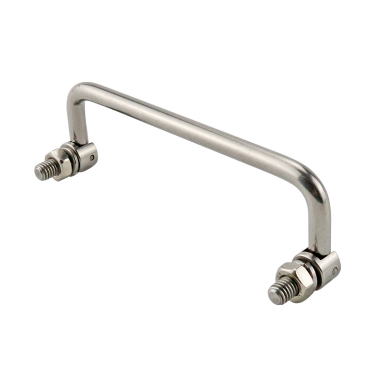
After these fields are defined, compare them with current drawings and controlled model data for round-bar torque hinge models. Do not reuse the old article’s broad torque table unless every value is tied to a current part number and drawing revision.
Validate the Sample in the Complete Assembly
Turning a loose hinge by hand is not an acceptance test. Install the sample in the production-intent housing, panel, fasteners, inserts, shaft interface, axial-retention arrangement, and opening-stop structure.
- Measure initial opening and closing breakaway torque under the defined condition.
- Measure running torque through the required angular range at the defined speed.
- Confirm that the panel holds at the required positions without unacceptable drift.
- Check for rebound, sudden release, excessive closing effort, or a sharp starting peak.
- Inspect the hinge body and output shaft for slip relative to the housing and panel.
- Check axial movement, panel gap, and end play after repeated operation.
- For dual hinges, inspect synchronization, binding, panel twist, and unequal load sharing.
- Inspect molded or thin-wall housings for cracking, creep, bore enlargement, or permanent deformation.
- Verify that the maximum-angle stop does not transmit uncontrolled impact into the hinge body, shaft, or housing.
- Repeat the torque, fit, retention, and stop inspection after the project-defined cycle and temperature profile.
The result should distinguish a preliminary supplier recommendation from sample approval and production approval. Record that distinction in the project documents without turning this article into a generic approval-process guide.
In-Line Torque Hinge Decision Workflow
- Confirm that a shaft-aligned embedded architecture fits the product (see “When an In-Line Torque Hinge Fits the Product”).
- Define the complete panel mass, center of gravity, axis, and additional loads (see “Define the Panel Torque Before Selecting a Hinge”).
- Set opening, closing, breakaway, running, holding, and tolerance requirements (see “Specify Torque Behavior and Measurement Conditions”).
- Package the body, shaft, bore, anti-rotation, axial retention, and stop interface (see “Define the Shaft and Housing Interface”).
- Resolve housing reaction, alignment, dual-hinge tolerance, and end-stop load (see “Prevent Housing Slip, Misalignment, and Stop Overload”).
- Define the cycle profile and end-of-life torque band (see “Define Cycle and Torque-Decay Acceptance”).
- Complete the drawing or RFQ fields before selecting a model (see “What to Put on the Drawing or RFQ”).
- Validate the complete installed assembly before releasing the production interface (see “Validate the Sample in the Complete Assembly”).
Composite Engineering Scenario
This is a composite engineering scenario created to explain the selection logic. It is not a customer project record or product test claim.
An OEM is developing an embedded industrial display panel with one cylindrical hinge at each side. The initial request says: “Use two 0.5 N·m in-line hinges.” The request does not state whether 0.5 N·m applies to each hinge or to the complete assembly, whether it is opening or closing torque, or whether it includes the breakaway peak.
The team first defines the finished mass, center of gravity, axis, and operating range. It then establishes the total target torque and a preliminary per-hinge band. The two hinges are not assumed to share the load perfectly; the prototype must verify left-right behavior.
The initial housing concept uses a smooth round bore in molded plastic. During fixture testing, the hinge body begins to rotate in the bore before the panel reaches the required starting torque. The design is changed to include a positive anti-rotation profile and reinforced local support.
The first dual-hinge assembly also shows higher operating torque than either loose hinge because the bores are not fully coaxial. The datums and bore process are revised, and the assembly is adjusted to avoid rigid over-constraint.
Finally, the maximum-angle stop is moved from the hinge interface to a reinforced structural feature so that opening impact does not pass through the torque mechanism. Only after the assembly meets the torque band, holding requirement, cycle profile, retention check, stop-load condition, and housing inspection does the team release the interface for production review.
FAQ
What is an in-line torque hinge?
An in-line torque hinge is a compact torque-generating mechanism arranged along the rotation axis. It is commonly integrated into a housing, panel, or embedded pivot through a cylindrical body and shaft interface. Its performance depends on the surrounding bore, anti-rotation feature, axial retention, alignment, and torque-transfer path.
Is an in-line torque hinge the same as a swivel torque hinge?
Not exactly. “In-line” describes a shaft-aligned packaging and mounting arrangement. “Swivel” is a broader catalog term for rotational hinge architectures. A specific round-bar model may be described by both terms, but its axis count, rotation range, torque direction, and interface must be confirmed from the drawing.
How do I calculate the torque required for a flip panel?
Start with the complete panel mass, center of gravity, hinge-axis location, installed orientation, opening range, and any additional resistance from cables, seals, springs, or latches. Gravitational torque is based on force multiplied by the perpendicular distance to the hinge axis. The final hinge target must also account for hinge quantity, operating feel, and project-specific acceptance limits.
Should torque be specified per hinge or for the complete assembly?
State both. Define the total torque required by the panel assembly, the number of hinges, and the target torque per hinge. Do not assume two hinges share the load equally without checking coaxial alignment, housing stiffness, manufacturing tolerance, and left-right synchronization.
Why does an in-line torque hinge rotate inside the housing?
Common causes include insufficient anti-rotation geometry, inadequate interference or retention, housing creep, weak plastic or thin-wall support, an incorrect bore tolerance, surface contamination, or a torque level that exceeds the housing interface. Both the hinge body and output shaft need defined torque-reaction paths.
Can I lubricate an in-line torque hinge?
Do not add a general lubricant unless the model-specific supplier instruction explicitly permits it. The hinge may depend on controlled internal friction, and added lubricant can change breakaway torque, running torque, holding behavior, noise, contamination, and torque decay.
Final In-Line Torque Hinge Specification
A reliable in-line torque hinge specification combines the required panel torque with a controlled shaft and housing interface. The drawing must define the fixed and rotating reaction paths, anti-rotation geometry, axial retention, alignment, torque direction, tolerance, angular range, opening-stop responsibility, and cycle acceptance.
Do not approve the hinge from one nominal N·m value or a legacy product table. Confirm model-specific data, install the sample in the real assembly, measure the required torque fields, and inspect the housing, retention, and stop features after the project-defined test profile.
Send HTAN the panel and hinge requirements, including the complete mass, center of gravity, axis drawing, torque direction, target torque band, body envelope, shaft interface, housing material, axial retention, opening-stop method, cycle profile, and acceptance criteria, for an in-line hinge configuration review.