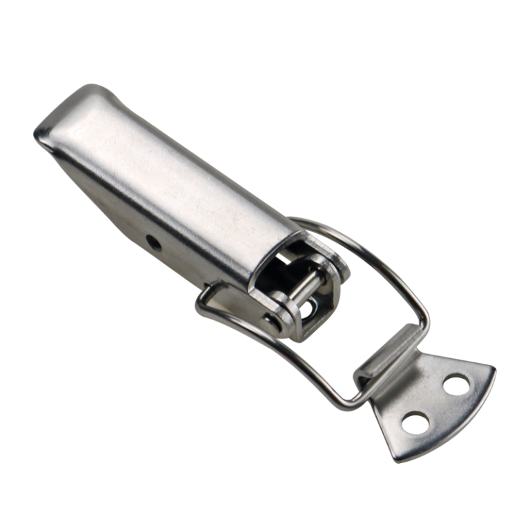
HTAN is one of the leading manufacturers of industrial hinges, handles and latches in China.


A machine access door can carry a hinge that looks substantial, closes cleanly on the assembly bench and still starts binding long before the stainless leaves show serious corrosion. The usual explanation is not one dramatic hinge failure. It is an accumulation: the door’s center of gravity sits farther from the axis than expected, the frame twists slightly after installation, several hinge axes do not line up, chips settle beside the knuckle, and coolant repeatedly reaches the pivot.
That is why stainless steel hinges for machine access doors should not be selected from door weight and material grade alone. The hinge is one part of a moving assembly that includes the door, frame, mounting joints, latch, seal, opening stop, cables and whatever the machine throws at the joint during production and cleaning.
This guide is deliberately limited to side-hinged access, enclosure and guard doors on industrial machinery. It does not cover a top-opening cover that must hold position, a counterbalanced hatch or a door that needs controlled closing torque. Those functions require a different mechanism decision before an ordinary hinge is considered.
What the hinge decision actually includes
- Where coolant, chips, mist, condensation and cleaning fluid can reach the hinge.
- The gravity-induced overturning moment created by door weight and center-of-gravity offset—not only total door mass.
- Hinge spacing, frame stiffness and the positional relationship among all hinge axes.
- The complete material stack: leaves, pin, bushing or bearing, retainer, fasteners and adjacent structure.
- Door sweep, gasket compression, latch engagement and clearance for service parts.
- How the production-intent assembly will be inspected and exercised before approval.
The Exposure Map Comes First
“Used indoors” is not an exposure specification. A hinge on the outside of a machine may stay comparatively dry, while another hinge half a meter away sits below a coolant leak or catches alkaline cleaner after every wash. Even hinges on the same door can live in different conditions: the lower one receives drainage and settled fines while the upper one sees mist and condensation.
Mark the hinge positions on the machine layout, then trace how contamination reaches each position. Look for direct spray, splash reflected from a workpiece, fluid running down the door skin, chips carried by the operator’s gloves, vapor that condenses during shutdown and cleaner trapped behind a mounting leaf. The useful question is not merely “Is the environment corrosive?” It is “What reaches this joint, at what condition, and where can it remain?”
| Exposure zone | Possible path to the hinge | Selection question | Evidence to obtain |
|---|---|---|---|
| Dry external face | Dust, handling residue and occasional wiping | Can the shape be reached and cleaned without driving debris into the pivot? | Installed photos, cleaning method and surface-finish specification |
| Mist or splash zone | Airborne coolant, reflected droplets or intermittent runoff | Which components are wetted, and can fluid drain instead of collecting? | Fluid identity, concentration, temperature, exposure pattern and complete material stack |
| Direct spray zone | Nozzle aim, hose cleaning or process spray | Is an exposed knuckle appropriate, or should the axis be shielded or relocated? | Spray direction, pressure category, duration and representative assembly evaluation |
| Chip collection zone | Falling swarf, fines carried by liquid or debris brushed from the door | Can chips bridge the gap, enter the pivot or block full closure? | Chip material, size range, shape, removal practice and clearance review |
| Condensation or washdown zone | Temperature cycling, detergent, rinse water and trapped moisture | Can the joint dry, and are crevices, fasteners and adjacent metals compatible? | Cleaning chemistry, temperature, dwell, rinse and drying conditions |
This exposure map prevents a common shortcut: choosing a higher stainless grade while leaving the pivot design, fasteners, retainer and trapped crevices unchanged. A grade change may be appropriate, but it cannot by itself stop chips from jamming a knuckle or cleaner from remaining under a leaf.
Coolant, Chips, and Cleaning Affect Different Parts of the Joint
Coolant at the pivot
A water-miscible metalworking fluid, a neat cutting oil and a process cleaner are not interchangeable exposures. Their formulations, concentration, contamination, temperature and contact time differ. The hinge review therefore needs the actual fluid product or a controlled chemical description, not the word “coolant.” If the fluid supplier changes during the machine’s service life, compatibility may need to be reviewed again.
The pivot is especially easy to overlook. The visible leaves may be stainless while the pin, washer, retainer or internal bushing uses another material. Fluid can also carry fines into the bearing interface and displace or contaminate lubricant. Ask the supplier to identify each wetted component and any lubricant or polymer that participates in movement.
Chips turn clearance into a wear path
Large chips may visibly block a door. Fine, hard particles create a quieter problem: they can collect at the knuckle, score a pin, become embedded in a softer bushing or prevent the leaves from reaching their intended closed relationship. Long stringy swarf can wrap around an exposed axis. Magnetic fines can also be drawn to nearby actuators or ferrous hardware and then migrate toward the joint during cleaning or door movement.
There is no single “chip-proof” hinge geometry. Shielding the axis, changing the hinge orientation, increasing access for cleaning, adding a deflector or moving the joint away from the chip path may be more effective than making the hinge larger. The right response follows from the actual chip shape and direction.
Cleaning changes the exposure
Cleaning does not merely remove contamination. It can force fluid into overlaps, strip lubricant, carry chloride-bearing residue from another part of the machine, and leave a concentrated film as water evaporates. A polished exposed surface may be easy to wipe, yet the backside of a mounted leaf can remain inaccessible. Review spray direction, detergent, concentration, temperature, contact time, rinse quality and the way the machine dries.
I would be cautious about any selection statement that promises “washdown resistance” without naming the complete assembly and cleaning conditions. That phrase hides too many variables. A sample exposed on the production-intent door under the defined cleaning cycle gives more useful evidence than a material label by itself.
Door Moment, Not Weight Alone
Door mass is necessary input, but it does not describe the gravity-induced overturning demand carried by the hinge support group. A narrow, dense door can place less moment on that support group than a lighter door with its center of gravity farther from the hinge line. Added windows, control devices, cable carriers, insulation and guards can shift the assembled center of gravity after the original door drawing was released.
Idealized vertical-door reaction model
M = W × e
- W is the weight of the complete moving-door assembly, expressed as force.
- e is the horizontal distance in the door plane from the hinge support line to the assembled center of gravity.
- M is the resulting gravity-induced overturning moment carried by the support group.
For an idealized vertical door with two effective hinge support locations separated by s, the magnitude of the opposing horizontal reactions is approximately:
R ≈ M ÷ s
The joints also carry vertical shear and any dynamic loads. This static relationship explains why center-of-gravity offset and effective hinge spacing belong in the inquiry; it is not a hinge capacity formula, does not determine load sharing among three or more hinges, and does not include frame movement, impact or axis misalignment.
The center of gravity should come from the assembled door, not a bare-sheet estimate. A window, operator panel, sound insulation or hardware mounted toward the latch edge can change both W and e. If the product family uses several door configurations, identify the most demanding configuration for each relevant load case instead of assuming the physically largest door is automatically worst.
The hinge group resists the moment through the spacing between support points and through the door and frame around the mounting zones. A wider vertical separation generally reduces the reaction couple, but only if the structure is stiff enough and the hinge axes actually align. Simply adding a third or fourth hinge does not guarantee better load sharing.
Define the unusual loads too. An operator may lean on an open door. A service technician may hang a tool pouch from it. The door may hit its stop during hurried access, vibrate while latched or experience acceleration during machine transport. These conditions do not justify inventing a generic safety factor; they justify identifying the project’s load cases and agreeing on how they will be assessed.
Hinge Spacing and Frame Stiffness Decide Whether the Axes Cooperate
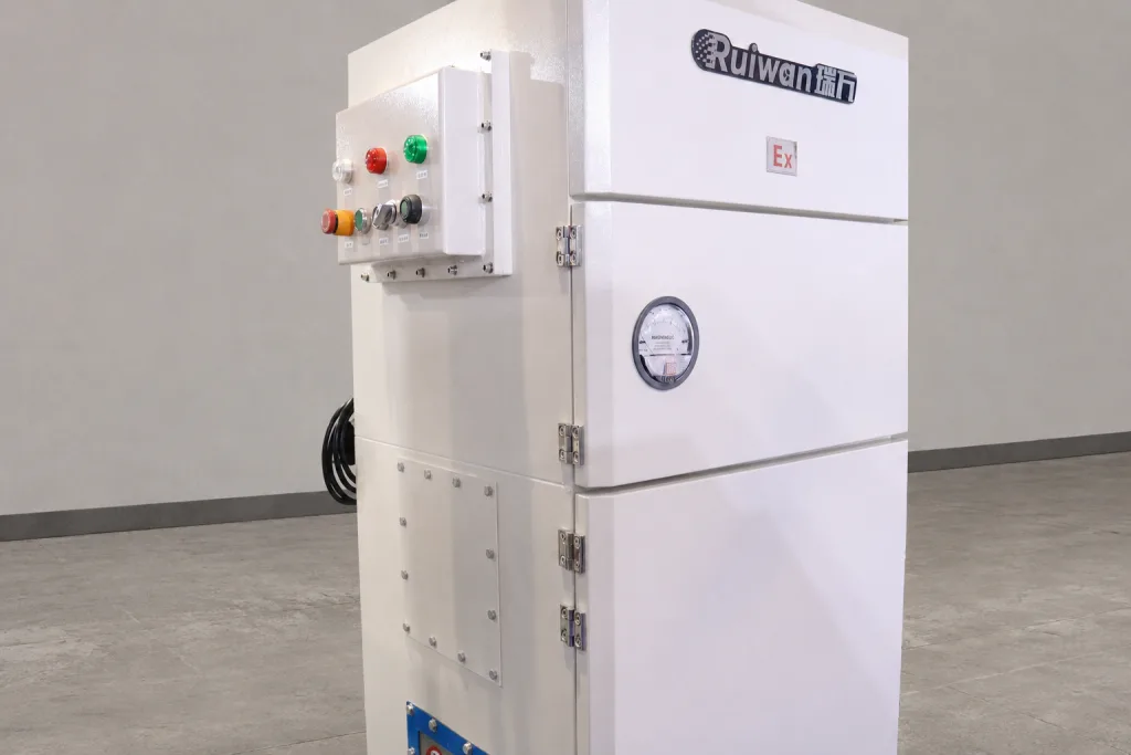
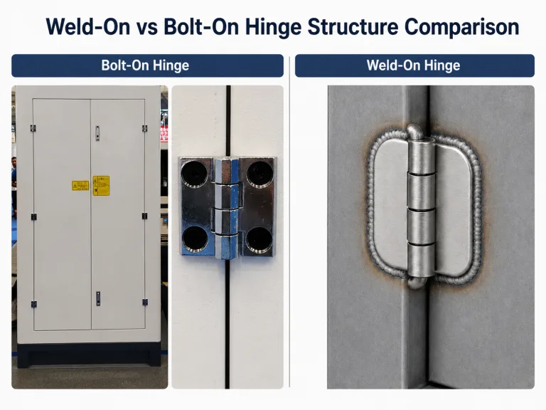
The photograph shows externally mounted hinges across several machine access doors. It does not verify hinge material, common-axis tolerance, load sharing or hazardous-area certification.
Multiple hinges share load only when their axes form a workable common line after the leaves are mounted. Hole position, weld distortion, formed-panel variation, coating build and frame twist all affect that line. If three hinges are individually placed from three local edges, the middle hinge can become a constraint rather than additional support.
This is one of the places where a technically “stronger” design can move worse. A rigid pin and closely fitted knuckle may tolerate less installation error than a looser joint. More clearance can reduce assembly sensitivity but increase play, sag or ingress. There is a real engineering conflict between accurate motion, load distribution, contamination tolerance and manufacturability; it should be settled on the assembled door rather than hidden inside a catalog capacity value.
Use a common hinge-axis datum on the door and frame drawings. Control the features that locate the hinge, not only the nominal hole centers within each leaf. If the mounting surface is formed, welded or painted, include those process effects in the tolerance review. On a long door, measure the frame in the condition in which the machine will operate, because anchoring and leveling can change the opening.
The structure around the hinge is part of the answer. A thick hinge leaf on a flexible return flange can still let the door drop. Backing plates, formed ribs or a stiffer frame member may be needed to distribute reactions. Conversely, a very stiff local reinforcement can transfer distortion to the next unsupported region. The useful drawing shows how force reaches the frame, not just where the hinge screws sit.
Build the Hinge Configuration From Four Separate Decisions
Hinge selection is not a six-way choice among surface-mounted, concealed, lift-off, bearing-supported, bolt-on and weld-on models. Those descriptions belong to different decision layers. One hinge can be surface-mounted, lift-off, bushing-supported and bolt-on at the same time. Build the configuration layer by layer, then review the resulting combination against the door and exposure.
| Decision layer | Option A | Option B | Approval question |
|---|---|---|---|
| Placement | Surface-mounted: visible installation and inspection, but exposed projection, fasteners, chip collection and cleaning access must be reviewed | Concealed: cleaner exterior and less external snagging, but internal sweep, hidden contamination and replacement access become critical | Which position gives the required motion and service access without placing the joint in a worse contamination path? |
| Door removal | Fixed or non-lift-off: resists unintended vertical separation, but complete hinge or fastener removal may be required for service | Lift-off or removable: simplifies planned door removal, but pin direction, removal position, accidental disengagement and door handling must be controlled | Must the door be removed in service, and can removal occur only under a defined safe procedure? |
| Pivot construction | Plain pin and knuckle: simple construction whose clearance, wear surfaces and contamination access still require review | Bushing- or bearing-supported: provides a defined bearing interface, but adds internal materials and possible lubricant compatibility questions | Which complete pivot stack has evidence for the stated load direction, duty and exposure? |
| Attachment | Bolt-on: replaceable and adjustable, but dependent on hole control, clamp stack, backing structure, retention and rear access | Weld-on: permanently integrated, but sensitive to fixturing, distortion, heat effects, surface restoration and repair access | Which attachment process can hold the common axis through production and service? |
The completed description should combine one decision from each applicable layer. “Stainless lift-off hinge” is still incomplete if the drawing does not identify placement, pivot construction and attachment. Likewise, “bolt-on hinge” says nothing about whether the door can be removed or how coolant reaches the pin.
For replaceable hardware or coated sheet-metal assemblies, the detailed bolt-on machine-frame door hinge guide covers joint stack, hole control and fastener retention after bolted attachment has been selected.
Where the hinge will be welded into a fabricated structure, use the separate welded machine-frame door hinge guide for fixturing, distortion and post-weld surface considerations. “Welded” is not automatically stronger in the installed machine; it is a different production and service choice.
The Axis Has to Survive the Drawing
A hinge drawing is incomplete if it shows only the leaf dimensions. The machine designer also needs the axis location relative to the door skin, frame opening, closed gap and seal. That position determines how the edge travels, whether the door clears a return flange, and whether a gasket is compressed or scrubbed as the door closes.
Draw the door at closed, partly open and required maximum-open positions. Include handles, latch parts, interlock actuators, windows, conduit, cables, hoses and protective-bonding conductors. A cable loop that clears in the open view can still pinch at an intermediate angle. A lift-off pin may be unobstructed in service position but impossible to withdraw beneath an overhead cover.
The opening stop also deserves its own load path. Do not make the hinge the stop by allowing its leaves, pin or knuckles to collide unless the selected model and mounting structure are explicitly designed for that function. A separate stop can keep impact out of the pivot, but its geometry and attachment still need evaluation.

For production control, identify the door and frame datums used to locate every hinge. Specify which surfaces are measured before and after coating. If slots are used for adjustment, define the permitted direction and the method that locks the final position. Uncontrolled “adjust at assembly” instructions often move variation into the latch gap or gasket compression.
The Stainless Label Is Not the Material Stack
A hinge described as stainless steel can contain several materials. Request the grade or material specification for the leaves, pin, washers, retainer and any load-bearing internal parts. If a bushing, bearing, coating or lubricant is present, identify it separately. Fasteners, backing hardware and the machine structure complete the electrochemical and mechanical joint.
Surface condition matters as well. Stamping, forming, welding, grinding, polishing, passivation and handling can change the exposed condition without changing the nominal grade. Iron contamination from shared tools, damaged protective surfaces and tight crevices beneath the leaf may govern what the maintenance team sees first.
304 versus 316 belongs to the exposure decision
Type 316 is not a substitute for mapping the coolant, cleaning and crevice conditions, and Type 304 is not automatically unsuitable for every machine. The detailed 304-versus-316 stainless hinge comparison explains the grade boundary. On this page, the approval requirement is simpler: name every relevant material and verify the complete joint against the real exposure.
Two standards boundaries worth keeping clear
If the access door functions as a machine guard, ISO 14120:2015 provides general requirements for the design, construction and selection of fixed and movable guards. Selecting a hinge does not by itself approve guard strength, risk reduction or an interlocking function, and the standard does not cover the interlocking device itself.
ISO 9227:2022 defines salt-spray test methods. It does not prescribe a universal exposure duration or acceptance criterion, and it is not intended to rank materials or predict long-term field life. A salt-spray result also does not establish compatibility with a particular machine coolant or cleaner unless the project has made and justified that connection.
Lubrication Without a Calendar
A fixed calendar instruction sounds practical but may be wrong in both directions. A clean, lightly cycled door may not need that intervention, while a hinge exposed to abrasive fines or repeated cleaning may need inspection much sooner. Some hinge designs are intended to run with a specific internal bearing system; adding an unrelated lubricant can attract chips, swell a polymer or conflict with the process.
Start with the hinge supplier’s model-specific instructions and the lubricant manufacturer’s compatibility information. Then set maintenance triggers from machine duty: operating cycles, contamination route, cleaning process, temperature, observed friction and the consequence of restricted access. Record the product, application point and amount where lubrication is permitted. More lubricant is not automatically better.
Condition is often more informative than a calendar alone. A change in opening force, metallic debris near the pivot, new play, a closing-gap shift, squeal or visible residue should prompt inspection. Cleaning staff should know which deposits to remove and which grease or protective film is intentional; otherwise a well-meaning wash can reset the joint to an unknown state.
Failure Clues on an Installed Door
Field symptoms rarely identify one cause by themselves. Use them to decide what evidence to collect before tightening, grinding or replacing parts. Changing the assembly first can erase the marks that explain why it moved.
| Observed symptom | Possible mechanisms | First evidence to collect | Immediate boundary |
|---|---|---|---|
| Door sags at the latch side | Mounting movement, local panel deformation, pivot wear, frame distortion or load change | Gap map, fastener witness marks, axis position, door mass and center-of-gravity changes | Do not assume a larger hinge alone will repair flexible structure |
| Door binds during part of the swing | Misaligned axes, frame twist, edge interference, contaminated pivot or cable contact | Opening-force trace by angle, rub marks, frame condition and cable/hose sweep | Do not grind the door edge before locating the constraint |
| Closed gap changes after operation | Joint slip, loosened fastener, permanent panel set, stop impact or latch pulling the door out of position | Fastener position marks, mounting-surface flatness, stop contact and latch engagement | Do not use latch adjustment to hide an unstable hinge joint |
| Metallic debris or increasing play | Pin or bushing wear, abrasive contamination, poor load distribution or loss of lubrication | Debris location, material identification where practical, pivot clearance and exposure history | Clean and inspect before adding lubricant |
| Local staining or corrosion | Trapped chemical, mixed-metal joint, iron contamination, damaged surface or inaccessible crevice | Photographs before cleaning, fluid path, residue or chemistry information and component materials | Do not label every brown mark as base-metal failure |
| Fastener heads or washers have moved | Loss of clamp load, panel embedment, vibration, incorrect joint stack or repeated overload | Witness marks, torque-control record, thread engagement and panel condition | Retightening alone may repeat the failure |
The drawing fits. The door still binds.
An illustrative engineering scenario
A side access door is drilled to the nominal hinge dimensions, and each hinge fits its local holes. After the painted frame is assembled and anchored, the door becomes tight through the middle of its swing. The hinge axes were never controlled from one common datum: formed flanges, coating and frame twist have moved them just enough to oppose one another. Coolant mist then carries fines into the most heavily loaded pivot, so opening force continues to rise.
Replacing the hinges with a larger model would not address the primary geometry. A useful investigation would map the installed axes and door gap, temporarily isolate any cable or hose interference where permitted, inspect the pivot for debris, and compare the frame before and after anchoring. The corrective action could involve locating features, assembly sequence, frame stiffness, controlled adjustment or hinge architecture—not merely more material.
This is an illustrative engineering scenario, not a customer project record or product test claim.
Prototype Validation Has to Use the Real Door
A hinge can pass a component-level load test and still fail the machine-door task because the panel, frame, latch or contamination path was absent from the fixture. Validate the production-intent assembly: real door and frame geometry, final coating or surface treatment, selected fasteners, backing hardware, gasket, latch, opening stop and representative attached equipment.
Begin with a documented baseline. Record door mass and center of gravity, closed-gap measurements, opening force by angle, free play, hinge-axis relationship, fastener condition and latch engagement. Exercise the door through the project-defined duty while applying relevant orientation, vibration, coolant, chips or cleaning conditions. The sequence matters; cleaning after contamination may produce a different result from testing each condition separately.
After exposure, repeat the same measurements and inspect the joint before cleaning away evidence. Look for movement at the leaves, wear debris, edge contact, surface changes, trapped residue and changes in seal or latch behavior. Define acceptance criteria before the test. “Still opens” is too vague when a door can open with rising force, increased sag or a compromised closing gap.
The dedicated machine-door hinge assembly validation guide covers the production-intent test plan in greater depth. Use that procedure to turn the component and installed-door evidence into project-specific acceptance criteria.
The Model Review Package
A request that says “heavy-duty stainless hinge for a machine door” forces the supplier to guess. A useful review package is not necessarily long, but it ties the selected model to the actual geometry and exposure. Send these inputs before asking for a final recommendation or sample approval.
- Door drawing with width, height, thickness and construction
- Assembled door mass and center-of-gravity location
- Required opening angle and complete sweep envelope
- Proposed hinge quantity, spacing and common-axis datum
- Door and frame mounting materials, thicknesses and finishes
- Bolt-on, weld-on, lift-off or concealed preference and why
- Backing structure, fastener access and replaceability requirement
- Latch, gasket, interlock, stop, cable and hose locations
- Coolant or process-fluid identity and operating condition
- Chip material, form, path and cleaning method
- Cleaner, concentration, temperature, dwell, rinse and drying process
- Operating cycle profile, vibration and foreseeable incidental loads
- Required material declarations, test evidence and acceptance criteria
- Representative sample and production-intent validation plan
The supplier drawing should then identify leaf geometry, pin or pivot construction, mounting features, tolerances needed for installation, material and finish by component, permitted load direction and any restrictions on mounting orientation. If a value is not supported by a controlled drawing or test condition, leave it as an open item rather than filling the gap with a generic catalog statement.
FAQ About Stainless Steel Hinges for Machine Access Doors
Does a stainless steel hinge automatically resist machine coolant?
No. Compatibility depends on the exact coolant formulation, concentration, contamination, temperature and contact time, as well as the materials in the leaves, pin, bushing, retainer, fasteners and lubricant. Map how fluid reaches and remains in the joint, then review the complete assembly with the fluid information.
Should I choose 304 or 316 stainless steel for a machine door hinge?
Neither grade is universally correct. The decision depends on coolant, cleaner, chlorides, crevices, drying, surface condition and every material in the joint. Type 316 may be considered for more aggressive chloride-bearing exposure, but a grade change does not correct chip ingress, axis misalignment or trapped chemicals.
How many hinges does a machine access door need?
There is no reliable universal number based on door height or weight alone. Review door moment, hinge spacing, frame and panel stiffness, axis tolerance, dynamic loads and the selected model’s evidence. Additional hinges help only when the installed axes and structure let them share the load.
Can a lift-off hinge be used on a machine access door?
It can be suitable when deliberate door removal improves service, but the design must control the lift-off direction, permitted removal position, door handling and any cables, hoses or bonding conductors. It should not allow accidental disengagement during normal machine operation or foreseeable loading.
Does an ISO 9227 salt-spray result predict hinge life around coolant?
No. ISO 9227 specifies salt-spray test methods; it does not supply a universal duration, acceptance limit or field-life prediction. Salt spray also does not reproduce a particular coolant, cleaner, chip load or installed crevice unless the project establishes a justified correlation.
What information should I send a hinge supplier?
Send the door and frame drawings, assembled mass and center of gravity, hinge-axis datum, hinge spacing, opening angle, mounting construction, latch and seal geometry, coolant and chip exposure, cleaning process, cycle and vibration conditions, service-removal needs, required evidence and planned installed-door validation.
Send the Machine Door Conditions, Not a “Heavy-Duty” Label
For a useful model review, send the door drawing, assembled mass and center of gravity, hinge-axis location, hinge spacing, mounting structure, required opening angle, latch and seal relationship, coolant and chip path, cleaning process and service-removal requirement.
Contact HTAN with the machine access-door application. We can compare hinge geometry against the stated conditions and identify which drawing details, samples and assembly checks still need confirmation before production approval.