






Industrial hinges, handles and latches for OEM equipment.
- +86 13720060320


Stainless Steel Draw Latch Selection Guide for Enclosures
An industrial enclosure can pass a first closing check and still have the wrong latch. The handle lies flat, but the keeper is only lightly engaged. A gasket settles, the panel moves within its normal tolerance, and the door starts to rattle. Reliable stainless steel draw latch selection cannot begin with a product photo or a material label; neither one prevents that failure.
Selection has to start with the closed assembly: the position of the latch and keeper, the movement required to seat the panel, the geometry that retains the handle after it crosses center, and the materials of every exposed component. A model can be stainless and still be unsuitable. It can also reach the keeper and still produce too little clamp travel.
Selection rule: do not approve a draw latch because it hooks onto the keeper. Approve the installed latch-and-keeper assembly only after it reaches the defined closed position, develops the required pull-up action, remains positively retained, and does not deform the panel or mounting area.
Stainless Steel Draw Latch Selection Starts With the Closed Assembly
A draw latch is only one part of the closure. The load path includes the latch base, handle, pivots, link or bail, keeper, mounting fasteners, door or lid, frame, and any gasket between the two surfaces. The first selection question is therefore not “Which latch looks large enough?” It is “What must happen between initial engagement and the final closed position?”
Define the two surfaces being drawn together. Record whether they meet metal-to-metal, stop against a hard spacer, or compress a gasket. Note which part is flexible, how frequently the enclosure is opened, and whether a person must see or feel that the latch is fully closed. These conditions determine whether a fixed, adjustable, compliant, or safety-retained configuration is an appropriate starting point.
| Assembly condition | What the latch must accommodate | Evidence needed before approval |
|---|---|---|
| Rigid metal-to-metal seam | A defined installation span and repeatable locked position without forcing the panels past their stops | Closed cross-section, latch drawing, keeper drawing, and operating check |
| Gasketed door or cover | Enough pull-up movement to seat the panel and compress the gasket without bowing the door | Gasket supplier guidance, panel stiffness review, and installed sample |
| Wide manufacturing stack-up | Controlled adjustment across the minimum and maximum assembly condition | Tolerance stack and verified usable adjustment range |
| Panel movement or gasket settlement | A design that retains useful preload as the assembly changes | Actual movement range and model-specific performance data |
| Mobile or vibrating equipment | Positive closed-position retention in addition to nominal pull-down action | Retention-feature review and assembly-level vibration validation |
The table identifies what the assembly is asking the latch to do; it does not approve a model. The supplier drawing must still show that the selected latch and keeper can work at the actual span, mounting orientation, and closed-panel relationship.
Over-Center Motion and the Locked Position
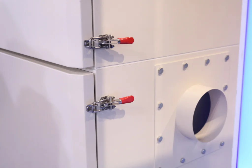
A typical over-center draw latch closes in stages. First, the hook, bail, or link engages the keeper. As the handle rotates about its pivot, the linkage draws the keeper toward the latch base. Near the end of travel, the linkage passes a geometric center condition. The handle then reaches its stop in the locked position.
This mechanism gives the operator mechanical advantage, but “over-center” should not be treated as a universal guarantee of self-locking. Retention depends on the exact pivot relationship, the amount of over-travel, elastic reaction from the panel or gasket, friction, wear, the handle stop, and any secondary catch. A latch that barely reaches the locked side of center may behave differently from the same latch installed at its intended geometry.
Three forces that must stay separate
- Operating force is what the user applies to move the handle. It changes through the stroke and is affected by leverage, friction, adjustment, and the panel reaction.
- Pull-down or clamping force is the force drawing the two assembly surfaces together in the installed geometry. It is not automatically equal to the force shown in a catalog under another name.
- Working or holding load is a supplier-defined allowable service load for a stated model and test arrangement. It must not be substituted for gasket compression force or treated as a universal pull-force rating.
Before comparing two models, request the definition behind each published value. The load direction, keeper, adjustment position, safety factor, and test fixture can change what the number means. If those conditions are not available, the value remains Supplier Confirmation Required.
Span, Grip Range, and Clamp Travel
Several catalog terms appear interchangeable until the latch is placed on a drawing. They are not. The supplier may also measure them from different surfaces or pivot locations, so the model drawing—not a generic definition—must control the final installation.
| Parameter | Engineering meaning | Required action |
|---|---|---|
| Installation span | The defined relationship between the latch mounting side and the keeper side in a stated position | Use the supplier’s datum and measurement convention |
| Grip range | The range of mounting-surface relationships that a specific latch configuration can accommodate | Check both ends of the assembly tolerance stack |
| Adjustment range | The available threaded or mechanical take-up used to set the latch | Maintain required thread engagement and locking provisions |
| Clamp travel or pull-up | The movement that draws the panel toward its final seated position after engagement | Match it to the real gap, gasket movement, and hard stops |
| Keeper offset | The lateral or vertical relationship between the keeper and latch load path | Verify alignment rather than relying on the link to bend sideways |
| Working load | A model-specific allowable load under stated conditions | Request the load direction and test basis |
| Operating force | The force needed to move the handle through engagement and lock | Evaluate on the complete assembly at tolerance extremes |
Review both ends of the assembly stack
Prepare a minimum-span and a maximum-span condition before approving the nominal setting. At the minimum condition, the latch must not bottom out, drive the panel past its hard stop, or over-compress the gasket before the handle reaches a stable locked position. At the maximum condition, the hook must still engage safely, provide useful pull-up, retain the required thread engagement, and cross into the intended locked geometry.
The stack should include formed-panel variation, frame tolerance, coatings, gasket thickness and recovery, keeper location, fastener clearance, and any credible assembly shift. Weld distortion or enclosure anchoring may also change the relationship after the individual parts pass inspection. If the minimum and maximum conditions are not known, model approval remains Engineering Review Required; a nominal catalog fit is not sufficient evidence.
An adjustable link can change reach and preload, but it does not create unlimited clamp travel. Extending a threaded hook until it catches the keeper may leave insufficient thread engagement, place the linkage outside its intended geometry, or make the locked position sensitive to small panel changes. Adjustment is a setup function, not permission to ignore the installation envelope.
An illustrative installation conflict: a designer selects an adjustable latch because its maximum reach covers the nominal span. At assembly, the hook reaches the keeper and the handle closes, but most of the movement is consumed before the panel seats. The door still floats against the gasket. More adjustment increases handle force without creating the missing panel travel. The nominal range looked correct; the closure behavior was not. This is an illustrative engineering scenario, not a customer project record or product test claim.
When the assembly varies because of gasket settlement, thermal movement, or production stack-up, decide whether controlled adjustment or compliant spring action is actually needed. The separate comparison of adjustable and spring latches covers that mechanism choice in greater depth.
Keeper Geometry Controls the Fit
The keeper is not a generic accessory added after latch selection. It establishes the engagement point and completes the load path. The same latch body can develop a different handle position, pull-up movement, and side load when paired with another keeper or installed at another offset.
Start with the supplier’s intended latch-and-keeper combination. Some keepers are supplied with the latch; others require a separate part number. A hook intended to engage a formed keeper should not be approved against a convenient hole, stud, or fabricated bracket unless the supplier confirms that interface and the assembly is validated.
Put the keeper on controlled datums
- Show the final closed relationship between the door or lid and the frame.
- Dimension the latch base and keeper from stable assembly datums, not from a flexible sheet edge.
- Identify the keeper part number, material, finish, orientation, and mounting method.
- Show lateral offset, engagement depth, handle sweep, and hook release path.
- Evaluate the minimum and maximum panel stack rather than only the nominal drawing.
Engagement also has an approach and release envelope. The hook must clear the keeper during opening, and the handle must complete its sweep without striking a return flange, neighboring enclosure, cable, shelf, or operator guard. A design that requires the user to bend the link sideways or lift the door to release it is already transferring an uncontrolled load into the mechanism.
Review how keeper load enters the frame. A tall or narrow bracket can rotate under an eccentric pull even when the latch base is rigid. Shims are acceptable only when they are controlled production parts with defined material, thickness, location, and retention. Loose setup washers should not become an undocumented method of setting clamp travel.
The link or bail should approach the keeper without being forced sideways. Visible rubbing on one edge, a twisted link, or a keeper that pulls out of plane indicates a geometry problem. An adjustable hook may compensate for intended span variation; it should not be used to pull a warped door into alignment or to correct uncontrolled lateral offset.
Stainless Steel Is an Assembly Decision
“Stainless steel draw latch” may describe the visible body while leaving the material of the pins, rivets, spring, keeper, or fasteners unclear. Corrosion can begin at those smaller parts or in the crevice beneath the mounting base even when the handle still looks acceptable.
| Assembly element | Question to resolve | Acceptable evidence |
|---|---|---|
| Latch body and handle | Exact alloy, forming condition, and surface finish | Controlled drawing, material specification, or supplier declaration |
| Hook, bail, or link | Alloy, adjustment thread, welds, and exposed contact surfaces | Part drawing and material identification |
| Pins and rivets | Whether the pivot materials match the environment and expected wear | Bill of materials or supplier confirmation |
| Spring or secondary catch | Material, protected location, and corrosion exposure | Component specification and sample inspection |
| Keeper | Whether its alloy and finish match the latch and service conditions | Separate keeper part number and material data |
| Mounting fasteners | Material compatibility, thread system, and locking method | OEM fastener specification |
Type 304 and type 316 are useful starting points, not universal environment labels. Chloride deposition, cleaning chemicals, temperature, time wet, crevice geometry, surface contamination, and natural rinsing all affect corrosion behavior. Type 316 is often considered when chloride exposure is more severe, but that statement does not approve an unknown latch assembly for marine, coastal, or washdown service.
Surface finish matters for cleanability and corrosion initiation, but a polishing or passivation description cannot compensate for the wrong alloy or a hidden carbon-steel component. Ask whether the stated finish applies to every stainless component, whether fabrication contamination is controlled, and whether water can drain from the mounted assembly.
If salt-spray evidence is requested, define what the result must prove. ASTM B117 specifies the apparatus, procedure, and conditions for a salt-fog environment; it does not prescribe the product-specific exposure period, specimen, allowable corrosion, or interpretation of results. Those acceptance conditions remain project-specific.
Panel, Gasket, and Mounting Behavior
A stronger latch does not make a weak mounting surface stronger. Thin sheet can dimple beneath the latch base, fastener holes can elongate, and a narrow keeper bracket can rotate before the latch reaches its intended load. That movement changes the effective span and reduces repeatability.
Watch the local structure: if the latch closes by bending the panel, the apparent clamp travel includes uncontrolled sheet deformation. Increasing latch preload can make alignment, fatigue, and sealing less stable rather than more secure.
Review the latch-base footprint, keeper support, panel thickness, backing plate or formed reinforcement, fastener access, and edge distance. The fastener specification must match the substrate and service load. A supplier’s latch rating does not validate a screw installed in thin sheet or a bracket with insufficient stiffness.
Closing Preload Is Not the Service Load
The force that seats a panel is not automatically the load the latch must carry in service. A draw latch normally pulls two parts together and maintains a defined closed relationship. Door weight, cover weight, sustained shear, impact reaction, and pressure load may follow different paths. Unless the latch drawing and assembly design explicitly assign those loads to the latch, hinges, stops, guides, frame members, or dedicated supports should carry them. Otherwise, the hook and keeper can become an unintended structural support, changing alignment and operating force as the enclosure moves.
Multiple latches also do not guarantee equal load sharing. Panel stiffness, keeper position, mounting tolerance, gasket response, and adjustment setting can make one latch engage earlier or carry more reaction than the others. Dividing a total service load by the number of latches is therefore not an approval method. Define the load direction, identify the intended structural load path, and review the least favorable assembly condition.
For a long door or multi-latch cover, check whether each latch closes without using the handle to lift, twist, or straighten the panel. Verify the assembly after welding, anchoring, and gasket installation, because those operations can change which latch engages first. Any proposed working-load margin remains model- and fixture-specific and requires supplier data plus assembly validation.
For a gasketed enclosure, obtain the gasket supplier’s compression guidance and define the closed hard-stop condition. Latch spacing and panel stiffness control whether compression remains even along a long edge or around corners. Do not assign a universal spacing value without the door geometry, gasket response, and pressure or sealing requirement.
A latch is not independently “IP65” or “IP66” simply because it pulls a door closed. If enclosure sealing is the primary task, review the complete sealing system and the separate guidance on compression latches for enclosure sealing before approving the latch family.
Vibration Requires a Separate Retention Review
Vibration can act at several interfaces: the handle may move toward release, a threaded adjustment may rotate, mounting fasteners may lose preload, or the panel may move against the gasket and keeper. Over-center geometry addresses only part of that system.
For mobile or vibrating equipment, identify the feature that resists reverse handle movement. Depending on the model, that may be a secondary catch, locking pin, spring feature, tool operation, padlock provision, or another positive retention method. Also define how the adjustment is locked and how the mounting fasteners are retained. These features are model-specific and should not be assumed from the words “toggle latch.”
Detailed selection by vibration severity, access frequency, gasket behavior, and anti-loosening method belongs in the guide to draw latches for vibration equipment. This stainless-steel article only establishes the material and installation information that the vibration review must carry forward.
A Closed Handle Can Still Be Wrong
The fastest way to find a poor selection is to inspect what the complete assembly does, not just whether the handle reaches its stop. The following observations point to different geometry, mounting, or material problems.
| Observed evidence | Likely assembly issue | Next check |
|---|---|---|
| Handle lies flat, but the panel can still move | Insufficient useful pull-up, excessive gap, or a hard stop reached too early | Measure engagement-to-seat movement and compare it with the model’s defined pull-up |
| Closing force rises sharply before the handle locks | Keeper too close, excessive gasket compression, interference, or poor alignment | Inspect the closed stack, handle path, and contact marks |
| Handle returns toward open after release | Linkage has not reached a stable locked position or elastic reaction is driving reversal | Review over-center position, handle stop, and secondary retention |
| Hook or bail rubs one side of the keeper | Lateral offset, nonparallel mounting, or a twisted bracket | Inspect latch and keeper from controlled datums |
| Sheet dimples around the mounting screws | Insufficient local stiffness or poor load distribution | Review reinforcement, base support, and fastener arrangement |
| Rust appears at pivots while the handle remains bright | Mixed materials, contamination, trapped moisture, or an unverified internal component | Obtain the complete material list and inspect crevice locations |
| Gasket contact is good near the latch but weak at corners | Panel bowing, unsuitable latch spacing, or an uncontrolled hard-stop condition | Map the full sealing line under the installed closing load |
Do not correct every symptom by tightening an adjustable hook. Extra preload can hide a gap during a bench check while increasing panel deformation, operating effort, and wear. Return to the closed-section drawing and identify which movement is intended and which movement is structural deflection.
Installation and Sample Review
A production drawing should locate the latch and keeper, but a representative sample must confirm the motion. Use the actual panel construction, gasket, hard stops, reinforcement, and mounting method wherever possible.
- Build the closed stack. Establish the final door-to-frame relationship with the intended gasket, spacers, coatings, and hard stops.
- Locate from datums. Position the latch base and keeper using the drawing references that production will control.
- Engage without forcing. Confirm that the hook or link approaches the keeper freely before the handle begins to pull the surfaces together.
- Observe the full stroke. Watch the handle, link, keeper, panel edge, gasket, and mounting bases through engagement and lock.
- Inspect the locked position. Confirm useful pull-up, stable retention, thread engagement, hand clearance, and release clearance.
- Check the structure. Look for sheet deformation, fastener movement, keeper rotation, link rubbing, and uneven gasket contact.
- Review tolerance extremes. Repeat the check at credible minimum and maximum stack conditions rather than approving the nominal assembly alone.
Include the operator in the sample review. Check finger clearance, glove access where required, pinch points, visible or tactile closed-position feedback, and the risk of clothing or nearby equipment snagging the handle. A padlock loop or secondary catch changes security and release behavior, but it does not replace a machine-safety interlock when the project requires one.
Record the latch and keeper part numbers, drawing revisions, installation span, adjustment setting, mounting method, open and locked photos, and any measured operating result required by the project. If cycling, corrosion, vibration, or environmental testing is required, define the specimen, condition, duration, inspection method, and acceptance criteria before the test begins.
A catalog review can support a preliminary recommendation. The production decision still depends on the approved sample, controlled drawings, and project acceptance criteria. Where these are missing, mark the result Engineering Review Required or Sample Approval Required rather than inventing a margin.
Drawing and RFQ Inputs
A usable request does not begin with “quote a heavy-duty stainless latch.” It gives the supplier enough assembly information to identify the correct mechanism, keeper, material, and mounting envelope.
| RFQ or drawing field | What to provide | Why it changes selection |
|---|---|---|
| Application and closure | Door, lid, hatch, cover, case, or removable panel; opening direction and access frequency | Defines operation, visibility, and service needs |
| Closed cross-section | Door, frame, gasket, hard stops, coatings, and adjacent structure | Establishes the real seated relationship |
| Latch and keeper datums | Controlled mounting surfaces and nominal/minimum/maximum span | Determines whether the model fits through tolerance |
| Required pull-up behavior | Gap at engagement, intended gasket movement, and final hard-stop condition | Separates reach from useful clamp travel |
| Load definition | Direction and purpose of any requested holding, pull-down, or service load | Prevents comparison of unrelated ratings |
| Retention requirement | Standard over-center action, secondary catch, padlock, tool operation, or other positive retention | Controls accidental release and service access |
| Operating environment | Indoor/outdoor use, water, chloride, cleaning chemicals, temperature, contamination, and time wet | Controls full-assembly material and finish review |
| Mounting structure | Panel material, thickness, reinforcement, fastener system, and rear access | Determines whether the installed load path is credible |
| Approval evidence | Required drawing, material declaration, sample, test report, or inspection record | Defines what the supplier must return before approval |
If a standard model is the preferred route, compare the available draw latch product range only after these inputs are defined. Product dimensions and published loads must be checked against the matching model drawing and keeper, not transferred from another series.
Ask the supplier to return the latch and keeper part numbers, drawing revisions, material and finish for the complete assembly, usable adjustment limits, published load definition, installation notes, and any required safety-retention option. Unknown information should remain Supplier Confirmation Required.
Questions Before Model Approval
Are all draw latches over-center latches?
No. Over-center action is common in toggle-style draw latches, but draw-latch families also include adjustable, spring, flexible, concealed, and other mechanisms. Review the actual linkage and closed-position retention shown on the model drawing.
What is the difference between grip range and clamp travel?
Grip range describes the installation relationships a model can accommodate. Clamp travel or pull-up is the movement that draws the panel toward its final seated position after engagement. A latch can have enough reach while still providing too little useful pull-up.
Should an industrial draw latch use 304 or 316 stainless steel?
There is no universal answer. Review chloride exposure, cleaning chemicals, temperature, crevices, surface condition, drainage, and the materials of the pins, spring, keeper, and fasteners. The exact grade and finish remain project- and model-specific.
Can an adjustable draw latch correct misalignment?
It can compensate for the intended span range defined by its design. It should not be used to pull a warped panel straight, correct uncontrolled lateral offset, or force a noncoplanar keeper into line unless the model is designed and approved for that geometry.
How much clamp travel does a draw latch need?
The required movement depends on the gap at initial engagement, intended gasket seating, hard stops, panel deflection, and assembly tolerance. Use the supplier’s pull-up definition and validate the complete assembly at its credible minimum and maximum stack conditions.
Is a stainless steel draw latch waterproof or vibration-proof?
Not by itself. Water ingress depends on the enclosure joint, gasket, panel stiffness, latch spacing, and installed compression. Vibration performance also depends on closed-position retention, adjustment locking, mounting security, and assembly-level validation.
Send the Closed-Assembly Drawing for Model Review
For stainless steel draw latch selection, provide the door-and-frame cross-section, latch and keeper datums, panel or gasket stack, mounting material, operating environment, access frequency, and any positive-retention requirement. HTAN can compare those inputs with available stainless steel draw latches and identify the information that still requires engineering or sample confirmation.