






Industrial hinges, handles and latches for OEM equipment.
- +86 13720060320


Industrial Cabinet Door Hinges: Mounting, Alignment and Load Path
Industrial cabinet door hinges can be mechanically capable and still produce a poor door assembly. A hinge may fit the drawing, carry the intended door mass in a supplier fixture and rotate smoothly by itself, while the finished cabinet develops latch-side drop, binding or local sheet-metal distortion. The missing question is usually not “Is the hinge strong enough?” but “What structure is the hinge actually mounted to?”
For a vertical side-hinged cabinet door, the hinge is one link in a structural chain. Door skin, formed returns, stiffeners, fasteners or welds, hinge leaves, pin axis and frame flange all participate in the load path. If one mounting zone moves, the hinge axis moves with it. A stronger-looking hinge cannot recover stiffness that the cabinet never provided.
This page focuses on that interface. Use it to define the door and frame mounting structure, establish one hinge axis, place the hinges in supported regions and prepare a cabinet drawing that can be reviewed against an actual hinge model. General mechanism selection belongs in the industrial hinge selection guide; this page starts after the project is already a vertical cabinet-door problem.
The Door Edge Is a Structural Member
A cabinet door should not be reduced to height, width and bare-panel weight. The hinge-side edge may be a folded return, a channel, a hem, a welded frame, an internal bracket or a combination of these features. Door-mounted equipment can change both the assembled mass and the stiffness distribution.
A window, HMI, cooling fan, handle, lock rod, insulation panel, cable carrier or internal bracket may shift the assembled center of gravity away from the hinge line. The same additions can make one part of the door stiffer while leaving the hinge attachment on a relatively flexible flange. The resulting door does not behave like the flat sheet shown on an early concept drawing.
The frame side deserves the same treatment. A hinge attached beside a formed corner can feed reaction into a relatively stiff junction. Move the same hole pattern onto a narrow unsupported return and the local flange may twist before the hinge body reaches its own mechanical limit.
Formed returns change the edge stiffness
A return flange is not only a convenient place to drill holes. Its depth, bend direction and connection to the rest of the door determine how the hinge reaction enters the panel. A short return may behave almost like an unsupported tab. A deeper return tied into a second bend or internal channel can create a much stiffer edge. Two doors with the same outer dimensions and sheet thickness can therefore need different hinge mounting details.
Corner cutouts deserve attention as well. If the hinge sits close to a notch, ventilation opening, seam or termination of a reinforcing channel, the local section can lose stiffness exactly where the leaf is trying to transfer load. The product footprint may still fit. The structural footprint may not.
When a stiffener is present, show where it actually starts and stops. A drawing that says “reinforced door” without locating the reinforcement relative to the hinge holes leaves the most important part of the interface undefined.
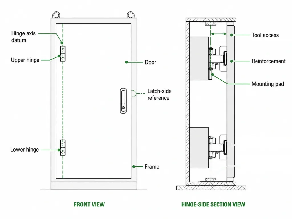
Useful first drawing: make a hinge-side section through the closed door and frame. Show the real bends, returns, local reinforcement and mounting access. A front view can show where a hinge sits. The section shows what actually supports it.
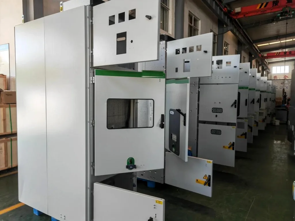
Industrial Cabinet Door Hinges and Mounting Surfaces
The door-side leaf and frame-side leaf do not mount to an abstract “cabinet.” Each one lands on a specific surface with a specific thickness, bend geometry, access condition and stiffness. Those two surfaces should be identified before a hole pattern is accepted.
Door-side interface
The door-side mounting face may be a flat skin, a folded return, a reinforcing channel, a locally doubled sheet or a dedicated bracket. The practical question is whether that region stays stable when the door is hanging open and when an operator pushes or pulls at the latch edge.
A wide leaf does not automatically solve a thin-panel problem. If the sheet underneath bows as fasteners are tightened, the mounting face has already changed before the cabinet enters service. If the leaf crosses a bend or an uneven surface, clamp load may concentrate at only part of the footprint. The hinge can be rigid. The substrate can still move.
Frame-side interface
The frame side must support the opposite half of the same load path. Check whether the flange is tied into a corner or stiffener, whether a nut or backing plate is reachable, and whether the mounting surface will remain flat after welding or coating. A threaded hole in thin material may locate a leaf accurately on the screen but provide little resistance to local deformation in the finished cabinet.
Tool access belongs in this review. A bolt pattern that can be manufactured is not necessarily a bolt pattern that can be assembled after rails, cable ducts or other cabinet hardware are installed. If the rear fastener cannot be reached, the attachment method needs to change before the hinge model is released.
The leaf needs a flat, repeatable seat
A hinge leaf should bear against the intended mounting surface without rocking across a bend, weld bead, raised seam or distorted edge. If tightening the hardware is what pulls the leaf flat, the joint is using fastener preload to correct cabinet geometry. That can hide a fit problem during assembly and reappear later as the sheet relaxes or the door begins cycling.
Countersunk hardware needs the same caution. The screw head can locate itself neatly in the leaf while the substrate beneath the hinge is still too thin or too flexible to hold the mounting plane. The fastener style should not be mistaken for a structural solution.
Where a hinge sits close to a sheet edge or bend, confirm that the surrounding material leaves enough room for the joint to develop without tearing, curling or interfering with the formed return. The exact limit depends on the material, thickness, hole type and attachment method, so it should come from the project drawing or supplier detail rather than a generic edge-distance rule copied between cabinets.
One Axis, Several Mounting Points
Two or three hinges on one door are expected to rotate around one common centerline. That sounds obvious. It is also one of the easiest requirements to lose during sheet-metal fabrication and assembly.
The upper frame pad may sit slightly farther forward than the lower pad. A long return may bow after forming. Welding can pull one mounting region. A hinge can then be forced into position so every screw still enters its hole. The assembly looks complete, but the pins are no longer working as a coaxial set.
Misalignment can appear as opening resistance, spring-back, localized wear, movement around fasteners or inconsistent latch engagement. The door may feel acceptable near the closed position and tighten farther through the swing because the leaves are being elastically forced into a path they do not naturally share.
The holes can match and the axis can still be wrong. Imagine an upper hinge mounted to a stiff corner return and a lower hinge mounted to a flatter region that has pulled during welding. Both hole patterns remain within their local dimensions, so the leaves bolt on without redrilling. When the screws are tightened, however, the lower leaf is pulled into alignment with the upper leaf. The hinge set now stores assembly stress. The door opens, but operating resistance rises and the latch position changes as the structure settles. This is an illustrative engineering scenario, not a customer project record or product test claim.
Use a stable cabinet datum to locate the hinge centerline and mounting faces. The drawing should control the relationship between upper and lower hinge positions, not merely dimension each hole group from nearby flexible sheet edges.
Datum control matters more than local hole accuracy
Each hinge can have an accurate hole pattern and the set can still be misaligned if those patterns are located from different moving references. On a tall cabinet, local dimensions taken from several formed edges can accumulate bend variation, weld pull and panel bow along the hinge line.
A better drawing strategy is to establish the functional hinge centerline from a stable cabinet reference, then locate the upper, middle and lower mounting features back to that same scheme. The goal is not tighter tolerances everywhere. It is tighter control of the relationship that affects rotation.
This distinction is useful during inspection. An inspector should not have to infer hinge-axis alignment from three separate local hole dimensions. The inspection plan should reference the same functional datum scheme used on the drawing.
Vertical Placement and Hinge Spacing
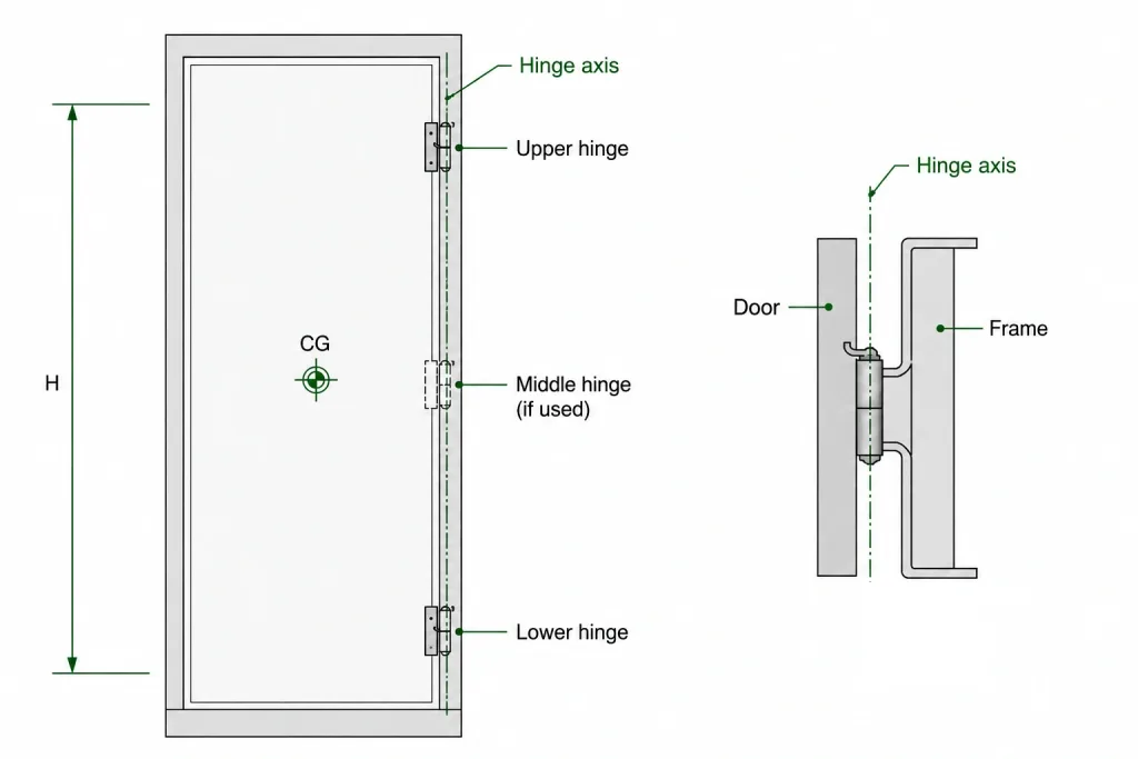
There is no useful universal rule such as “one hinge every X millimeters” for industrial cabinet doors. Door height matters, but so do assembled mass, center-of-gravity position, local stiffness, mounting geometry and the reactions introduced during operation.
The upper and lower hinge regions should be placed where the door and frame can actually transfer load. Moving them farther apart can improve the structural relationship on a tall door, but spacing alone does not strengthen an unsupported flange. If the upper mounting zone is stiff and the lower zone twists, increasing the distance between them does not make their behavior equal.
Door-mounted equipment can also change which region deserves reinforcement. A display or fan near the latch side shifts the assembled mass distribution. A heavy lock mechanism near the edge may create local deformation that is not visible in a bare-panel review.
A third hinge is not an equal-load divider
Adding a middle hinge can be useful for a tall or flexible door, but it should not be treated as an automatic capacity multiplier. Manufacturing variation changes when each hinge begins to carry reaction. If the middle pad is slightly high, low, forward or rearward, that hinge may be preloaded while another position carries less than expected.
Number of hinges is therefore a structural-layout decision, not simple arithmetic. The product drawing, cabinet tolerances and installed sample have to agree.
Reinforcement and the Load Path
Supplier hinge capacity does not automatically become cabinet-door capacity. A supplier may test a hinge on a rigid fixture with controlled fasteners and known spacing. A production cabinet may use folded sheet, spot-welded brackets or a narrow return. Those are different structures.
The useful load path is continuous:
assembled door → door mounting zone → hinge leaf → hinge pin → frame leaf → frame mounting zone → cabinet structure
If the door-side sheet dimples around a fastener, the hinge can remain intact while the latch edge moves. If a return twists, pin alignment changes. If a backing plate covers only part of the hinge footprint, the joint may rotate around the stiffened area instead of behaving like a rigid pad.
Reinforcement should spread reaction into a larger structural region. Simply adding a small thick plate beneath the leaf may create a stiff island surrounded by flexible sheet. The connection between that plate and the rest of the door matters as much as the plate thickness.
Where reinforcement earns its space
- The door skin deforms visibly while the hinge leaf stays flat.
- The formed return is narrow relative to the hinge footprint.
- Door-mounted equipment moves the assembled center of gravity outward.
- Fastener clamp load distorts the mounting face before the door is hung.
- A tall door needs hinge positions in regions that are not naturally tied into a stiff corner or channel.
Avoid an abrupt stiffness stop
Reinforcement that ends directly beside the hinge can move the deformation rather than remove it. The reinforced area stays flat while the adjacent sheet becomes the new rotation point. If repeated opening loads concentrate at that transition, the cabinet can develop movement just outside the plate or channel.
The reinforcement layout should therefore be reviewed as part of the door section. Ask where the reaction enters the stiffener, how the stiffener is joined to the rest of the door and where the stiffness changes again. A longer load path through several connected sheet-metal features is often more useful to understand than the thickness of one small plate.
Those observations do not define a universal reinforcement thickness. They identify where the project needs a structural review. Material, geometry, joining method and available space remain project-specific.
Attachment at the Hinge Line
Bolts, studs, rivets and welds are not interchangeable labels added after the hinge is selected. Each attachment changes the cabinet interface, available access and manufacturing tolerance.
Bolted and stud-mounted joints
Bolted joints can support replacement and adjustment, but the structure must provide bearing area and a repeatable locating surface. Rear access for nuts or backing hardware needs to remain available after the cabinet is populated. Studs can simplify the visible side, yet their protrusion and tool access still occupy space behind the mounting face.
Do not assume a larger washer solves a flexible flange. It may reduce local bearing stress while the complete flange continues to rotate.
Riveted joints
A riveted hinge can suit sheet-metal production where rear access or assembly speed favors that method. Hole condition, grip range, edge distance and substrate stiffness still determine whether the leaf remains located. The installation tool also needs physical access around the hinge barrel and adjacent cabinet features.
Welded joints
Welding removes some fastener-access constraints but introduces heat and fixture sensitivity. A hinge can be accurately located before welding and end up with a shifted axis after the frame or leaf pulls. Weld sequence, fixture support and post-weld axis inspection belong to the mounting plan.
The attachment question should end with one practical statement: how will this joint keep the hinge centerline where the drawing says it belongs?
Why the Latch Edge Drops
A door that sits low at the latch side is often described as a weak-hinge problem. That description is too broad to be useful. The visible symptom can come from the hinge, the mounting structure or the alignment between them.
| Observed Condition | Evidence to Inspect | Structural Question |
|---|---|---|
| Latch edge drops while hinge leaves remain visually intact | Door return, frame flange, fastener bearing marks, local sheet deformation | Is the mounting structure moving before the hinge body reaches its limit? |
| Door becomes tight through part of the swing | Upper/lower centerline relationship, witness marks, forced leaf position | Are the hinges operating on one axis? |
| Closed position changes after mounted equipment is added | Final assembled mass distribution and center-of-gravity shift | Did the production-intent door change the load path? |
| Fasteners remain tight but the leaf position shifts | Dimpling, elongated holes, bent flange or rotation of a backing plate | Is the substrate deforming beneath a tight joint? |
| Middle hinge shows unusual marks or wear | Mounting-pad height and fore/aft position relative to upper and lower hinges | Is the middle hinge preloaded by fabrication variation? |
The table is a diagnostic aid, not a failure verdict. More than one mechanism can appear at the same time. A flexible door can also be misaligned; a stiff frame can still have one poorly supported mounting pad.
This is also why a generic “hinge rated for the door weight” statement is incomplete. The rating may describe the hinge under one supplier test condition. The cabinet still has to preserve the axis and transfer the resulting reactions without unacceptable movement.
Cabinet Construction to Hinge Form
Once the mounting structure is understood, cabinet geometry can narrow the hinge forms worth investigating. This is not a product ranking and it does not replace model-level drawings.
| Cabinet Condition | What the Structure Demands | Hinge Form to Investigate |
|---|---|---|
| Thin formed door with a reinforced hinge edge | Leaf footprint must land on the reinforced region without distorting the skin | Fixed-axis form with a mounting footprint that matches the reinforced pad |
| Narrow door or frame return | Attachment width and fastener access are restricted | Narrow-leaf, offset or bracket-mounted form |
| Direct exterior mounting is available | Simple accessible load path is possible | External fixed-axis form |
| Exterior hardware must be minimized | Internal envelope must accept the mechanism and mounting hardware | Concealed form; use the dedicated concealed-versus-exposed comparison before committing |
| Door must be removed for service | Removal direction, support and clearance must be defined | Removable form after the service path is confirmed |
If the project is specifically deciding between hidden and visible hardware, use the concealed vs exposed hinge guide. That page owns the visibility, internal-envelope and service-access comparison. This page only checks whether the chosen arrangement can be supported by the cabinet structure.
If the cabinet is an electrical enclosure and the dominant question becomes door return geometry, gasket land, internal keep-out space, opening sweep or removable-door architecture, continue to the electrical enclosure hinge architecture guide. Those are enclosure-architecture decisions rather than cabinet mounting-structure decisions.
What the Cabinet Drawing Must Control
A usable cabinet-door drawing should let another engineer place the hinge into the real assembly without guessing where the load goes or how the axis is established. Overall hinge length and a hole pattern are not enough.
- Door height and width
- Assembled door mass
- Relevant center-of-gravity location
- Closed hinge-side door section
- Frame-side section
- Common hinge-axis datum
- Upper and lower hinge locations
- Any intermediate hinge location
- Door and frame mounting thickness
- Local reinforcement geometry
- Fastener, stud, rivet or weld location
- Rear tool and hardware access
- Latch-side closed position
- Required service-open position
The drawing should also separate supplier-controlled product dimensions from cabinet-controlled geometry. The hinge supplier can define the leaf, barrel, pin position and product hole pattern. The cabinet design controls the substrate, reinforcement, mating mounting surfaces and the relationship between hinge locations.
Protect the closed-door reference
The latch edge provides a useful functional reference because a small angular change at the hinge line can become a visible position change across the full door width. The drawing should therefore make clear which surfaces establish the intended closed position. If the latch is adjusted to compensate for a moving hinge line, the cabinet can appear corrected while the structural source remains.
Do not use the latch to force a misaligned door into shape. A latch can hold the closed position, but it should not be the device that straightens a twisted door or overcomes hinge-axis error every cycle. That condition increases the importance of checking the door immediately before latch engagement, not only after the latch has pulled it home.
Do not dimension the entire hinge line from a flexible edge if a formed corner or other stable datum is available. The goal is repeatable axis location after forming, welding, coating and assembly—not only nominal coordinates in CAD.
Validate the Finished Door Assembly
A hinge mounted to a rigid bench plate can confirm basic product geometry or motion. It cannot prove that the production cabinet preserves the same axis and support conditions. The useful sample is the representative door-and-frame assembly.
Include the intended door structure, reinforcement, attachment method, hinge spacing and major door-mounted components. Then inspect what the cabinet actually does.
- Closed position: the latch-side edge should return to the intended position without being lifted or pushed into alignment by hand.
- Opening behavior: resistance should not increase because multiple hinges are forcing one another onto different axes.
- Mounting zones: look for sheet dimpling, flange rotation, weld movement, fastener bearing marks or backing-plate movement.
- Repeatability: open and close the door repeatedly enough to see whether the initial position is stable. Any project cycle-life requirement needs its own defined test conditions and acceptance criteria.
- Service position: confirm the real cabinet reaches the required open position without the hinge line, nearby structure or installed equipment forcing the door out of alignment.
Do not convert a supplier load statement into a universal cabinet safety factor. Load direction, fixture stiffness, hinge spacing, fasteners, substrate and allowable deformation all affect whether a supplier result applies to this assembly. When those conditions are unknown, the capacity relationship remains subject to engineering review and representative sample approval.
Once the cabinet mounting structure is controlled, the industrial hinge range can be reviewed against a defined application instead of a generic “cabinet door” label.
Industrial Cabinet Door Hinge FAQ
How far apart should industrial cabinet door hinges be?
There is no universal hinge-spacing value. Use the actual door height, assembled mass, center-of-gravity position, frame stiffness and supported mounting zones. The upper and lower hinges should transfer reaction into stable structure while preserving one common hinge axis.
Does adding a third cabinet hinge automatically increase load capacity?
No. A third hinge changes the support arrangement, but it does not guarantee equal load sharing. Mounting-pad position, stiffness and axis alignment determine how the reactions are distributed, so the middle hinge may be preloaded or carry less than expected.
When does a sheet-metal cabinet door need hinge reinforcement?
Review reinforcement when the local door or frame sheet cannot keep the hinge mounting face stable. Dimpling, flange rotation, a narrow unsupported return, outward-shifted door mass or distortion during fastener tightening are signs that the hinge-line load path needs structural support.
Why can a cabinet door bind even when the hinge holes match the drawing?
Matching local hole dimensions does not guarantee one common hinge axis. Formed or welded mounting surfaces can shift relative to each other, and the leaves may be forced into position during assembly. The door can then bind because the hinge pins are not coaxial.
What information is needed to review an industrial cabinet door hinge mounting?
Provide the hinge-side door and frame sections, door dimensions, assembled mass, relevant center-of-gravity location, proposed hinge positions, mounting materials and thicknesses, reinforcement, attachment method, tool access and required service-open position.
Send the Cabinet Door Drawing
Provide the hinge-side door and frame section, assembled door data, proposed hinge positions, mounting thickness, reinforcement and required opening condition. Those inputs allow available hinge forms to be compared against the actual cabinet structure without inventing missing dimensions or capacity claims.
Industrial cabinet door hinges work as part of the door-and-frame structure. The practical design target is a stable mounting surface, one controlled axis and a load path that remains repeatable after fabrication and assembly.