






Industrial hinges, handles and latches for OEM equipment.
- +86 13720060320


Swing Handle and Rod Lock Installation: Cutout, Rod Length, and Multi-Point Alignment
The handle can reach “locked” while only one end of the door is actually pulled in.
A swing handle may rotate normally, the actuator may complete its travel, and both linkages may appear connected. The upper point can still engage first while the lower rod bows between its guides. The door looks closed. The gasket imprint and corner movement tell a different story.
A reliable swing handle rod lock installation therefore starts with the complete cabinet-door geometry: cutout, handing, actuator direction, upper and lower rod length, guide positions, keeper locations, door stiffness, and locked and unlocked travel.
This guide covers recessed swing handles that operate upper and lower rods for multi-point industrial cabinet-door closure. It begins after the mechanism has been selected. Projects still deciding between a single-point cam latch and a multi-point swing handle should use the quarter-turn cam latch vs. swing handle comparison. Stand-alone quarter-turn installation belongs to the cam latch installation guide. Compression latches, paddle latches, and external draw latches use different installation logic.
Safety boundary: isolate electrical equipment and follow the owner’s lockout and work-control procedures before cutting, drilling, or installing cabinet hardware. Do not machine or work inside an energized enclosure.
Swing Handle Rod Lock Installation Layout
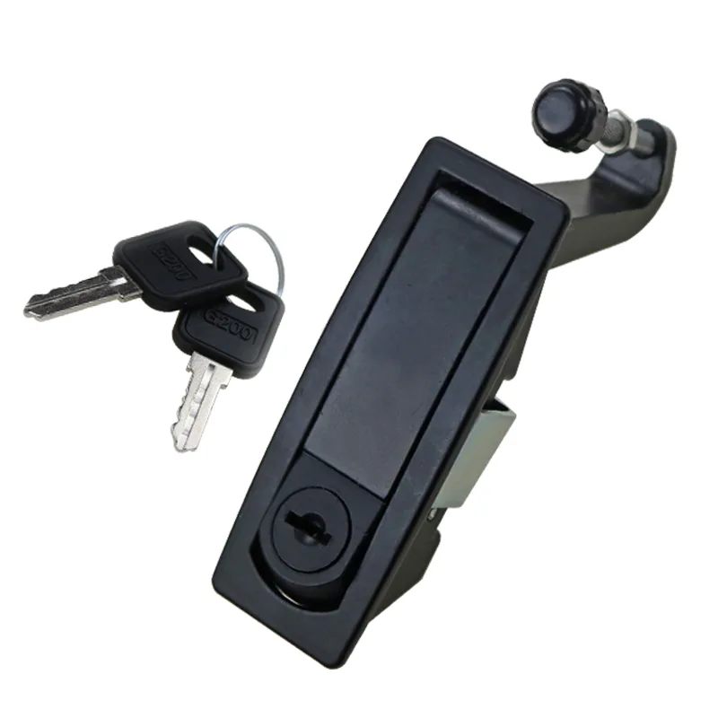
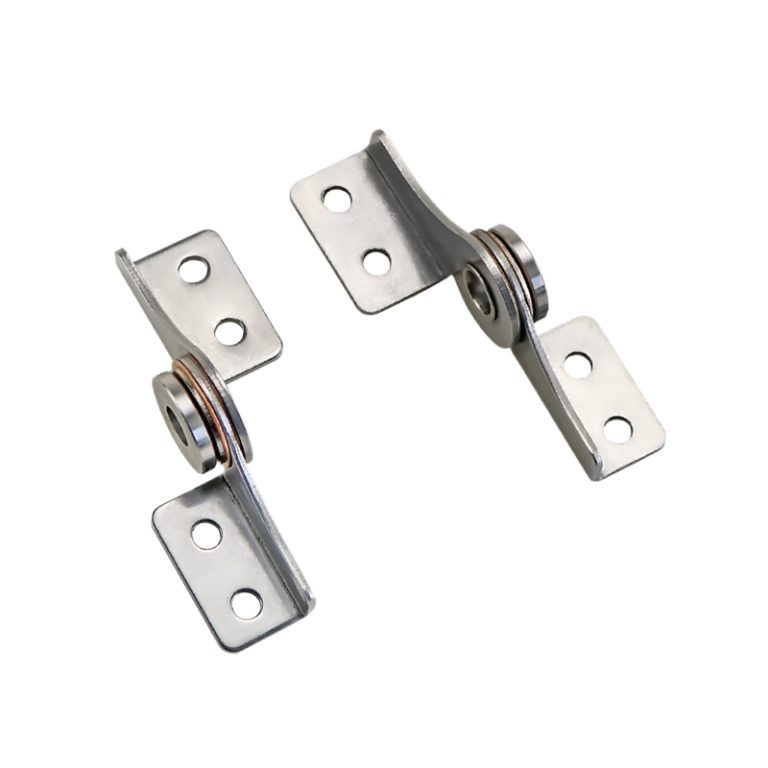
Typical swing handle component used in a rod-lock installation system.
A swing handle is only the visible operator. The installed locking system also includes the recessed housing, lock cylinder or tool insert, internal actuator or transmission, upper and lower rods, rod-end fittings, guides, top and bottom cams or rollers, keepers, retainers, and mounting hardware.
Two systems can look similar from outside the door while using different internal travel, linkage attachment, handing, guide geometry, and frame-side engagement. Start from the exact model and controlled drawing revision. Do not combine a handle from one assembly with rods, cams, or keepers from another because the parts appear to connect.
- Handle and housing: exterior operator, recess flange, lock cylinder or tool insert, and panel-retention features.
- Actuator or transmission: rack, crank, rotary actuator, cam-driven mechanism, or other assembly that converts handle movement into linkage travel.
- Upper and lower linkages: round rods, flat bars, formed members, threaded ends, clips, joints, and any length-adjustment features.
- Guides: supports that keep each rod aligned while allowing free axial movement.
- Remote locking points: cams, rollers, hooks, or pins that engage the top and bottom keepers.
- Keepers and frame interfaces: the structural surfaces that react pull-in and retention loads.
In this article, “rod” also includes flat-bar or formed linkages where the selected system uses them. “Keeper” means the frame-side engagement feature; it may be a separate bracket, strike plate, formed slot, or controlled opening in the cabinet frame.
Broad model browsing belongs to the industrial latches category. The installation work below assumes that the selected model, rod system, and operating style already suit the cabinet application.
Door Datums Before the Cutout
Do not place the handle from the overall door height alone. The visible center may be convenient, but it can conflict with the internal frame, stiffener, HMI, window, cable route, gasket channel, or the gearbox and rod envelope.
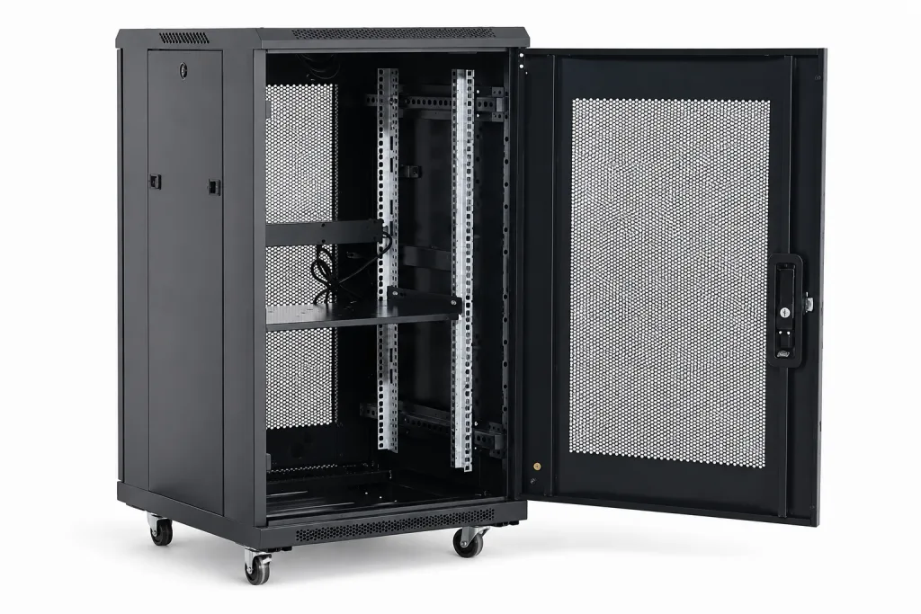
Establish the installation from the assembled door and frame:
- The hinge-supported closed-door position.
- The internal top and bottom frame or keeper datums.
- The intended handle and gearbox output centerline.
- The gasket contact plane and compressed-door position where applicable.
- The door reinforcement, hems, bends, ribs, and welds near the cutout and rod path.
- The internal equipment, rails, wiring, insulation, and service envelope.
- The required operating height and external key or tool access.
Establish the top and bottom engagement positions from one controlled closed-door coordinate scheme. If the upper point is located from the cabinet roof while the lower point is located from a nominal door length, fabrication and assembly tolerances can accumulate in different directions. The rods then inherit a mismatch that adjustment may not absorb.
Handing and Actuator Orientation
Left-hand and right-hand door labels are not enough by themselves. Record the hinge side while viewing the cabinet from the defined exterior, the direction in which the handle releases, and the actuator movement produced by that handle rotation.
A mirrored 3D model can make the outside handle look correct while reversing the cylinder orientation, actuator output, linkage-end direction, or remote cam engagement. Before the panel is cut, check the complete operating sequence:
- Door hinge side and outward opening direction.
- Handle position when locked and when released.
- Key-cylinder or tool-insert orientation in both states.
- Actuator movement at the upper and lower outputs.
- Whether the rods extend, retract, or move in opposite directions during locking.
- Top and bottom cam or roller orientation relative to each keeper.
- Whether the selected assembly is designed to be reversed or requires a handed version.
Cutout, Panel Stack, and Rear Clearance
The cutout must come from the exact model drawing. The visible recess does not define the opening, and a different swing handle may use another flange, anti-rotation feature, mounting-hole pattern, retaining bracket, or rear actuator depth.
Match five items before cutting:
- Exact model: handle, cylinder or tool insert, transmission, rod-end interface, and keeper set.
- Drawing revision: the released cutout profile, hole pattern, orientation, and datum location.
- Panel stack: skin, reinforcement, spacer, gasket, coating, and any double-wall construction clamped by the housing.
- Mounting hardware: rear bracket, screws, nuts, clips, washers, or formed retention features.
- Rear envelope: actuator depth, linkage connection, crank sweep, rod or bar offsets, fastener access, and clearance to internal parts.
Deburr and protect the finished opening without removing a locating flat, tab, corner radius, or anti-rotation feature. Do not use mounting screws to pull a distorted housing through an undersized opening. If the panel is thin or flexible, confirm whether local reinforcement is part of the approved stack rather than adding it after the rod geometry is fixed.
Install the Handle and Actuator
Keep the housing adjustable until its orientation and internal travel are verified. Final tightening too early can lock an error into the rod centerline.
- Match the received handle, transmission, rods, guides, end fittings, keepers, and hardware to the released model and drawing revision.
- Inspect the cutout, edge condition, coating repair, anti-rotation features, and mounting-hole location.
- Insert the housing in the specified orientation with the approved gasket, spacer, or sealing parts where supplied.
- Install the rear bracket or retainers lightly enough to preserve alignment adjustment.
- Attach the actuator or transmission according to the model-specific assembly arrangement.
- Move the handle through its travel and confirm that the upper and lower outputs move in the expected directions.
- Check that the housing, cylinder, and handle reach their intended locked and unlocked positions without forced overtravel.
- Complete the model-specific fastening only after the housing, actuator, and linkage centerlines are established.
Use a supplier torque or fastening instruction only when it belongs to the exact model, hardware, panel stack, and document revision. Additional screw torque is not a correction for the wrong cutout, a distorted door skin, or a misaligned rear bracket.
Upper and Lower Rod Length
Rod length is not one-half of the door height unless the actual mechanism, handle location, keeper geometry, and end fittings make it so. The upper and lower rods can require different finished lengths even when the handle looks visually centered.
Determine each rod from the installed mechanism and final keeper datums:
Measurement route: actuator output datum → rod-end connection → guide path → top or bottom cam/roller → keeper engagement position.
| Rod-Length Input | Why It Changes the Finished Rod | Installation Action |
|---|---|---|
| Actuator output datum | Defines the working start point for the upper or lower connection | Measure from the released actuator reference, not the visible handle center |
| Locked and unlocked output travel | Changes the remote cam position at both ends of operation | Record the actual output positions for the selected model |
| Top and bottom keeper datums | Set the required final engagement locations | Establish both from the production-intent closed door and frame |
| Rod-end fitting length | Uses part of the center-to-center distance | Include clips, threaded ends, clevises, bends, rollers, and joints |
| Thread engagement and adjustment | Determines usable correction range and retention | Maintain the minimum thread engagement defined for the selected rod end while preserving usable adjustment toward both shorter and longer settings |
| Remote cam or roller geometry | Changes where rod movement becomes keeper contact and pull-in | Use the exact end fitting and its controlled orientation |
| Guide path and offsets | A bent or offset path changes effective length and friction | Measure through the actual installed route, not a simplified straight line |
| Door and frame tolerance | Moves the remote keeper relative to the gearbox | Check minimum and maximum assembled conditions |
| Gasket-contact position | Changes the closed-door datum and final pull-in requirement | Set rod length with the production-intent gasket installed |
Do not apply a rod-length formula unless it belongs to the exact lock model and controlled drawing. Every variable, unit, output position, rod-end fitting, required thread engagement, keeper arrangement, and adjustment allowance must be defined before the result can be used for manufacturing.
For first-article work, leave controlled adjustment at both remote points when the model permits it. Do not consume the complete thread range to compensate for a wrong centerline or keeper position. A rod that fits only at the end of its adjustment range provides little room for production variation or service correction.
Rod Guides and Free Travel
The rods need support, but they also need room to move. Too few guides allow vibration, bowing, and impact against the door. Guides that are too tight create friction, prevent full travel, and make the upper and lower points appear out of synchronization.
- Keep the guide centerline aligned with the actuator output and remote end fitting.
- Place guides where they control rod bow without forcing the rod around door stiffeners or weld distortion.
- Check guide bore, slot, liner, or clip clearance through the full locked and unlocked travel.
- Keep rods clear of cable bundles, insulation, grounding straps, windows, and internal equipment.
- Allow for coating, contamination, temperature change, and door-panel deflection where they affect free movement.
- Inspect threaded joints, clips, retaining rings, and formed ends so they cannot drag through a guide.
- Confirm that service removal remains possible after the cabinet is fully populated.
A rod should not be used as a spring to pull a misaligned keeper into position. Visible bow in the locked state indicates that the system is storing alignment error rather than transferring motion cleanly.
Top and Bottom Keeper Alignment
Set the remote keepers from the final assembled door position, not from an empty frame and not from nominal CAD alone. Install the production-intent hinges, gasket, reinforcement, swing handle, gearbox, rods, guides, and remote cams or rollers first.
Move the handle slowly while watching both engagement points:
- Which end touches its keeper first?
- At what handle position does each remote point begin pull-in?
- Does either cam contact only the keeper edge?
- Does one keeper bracket bend before the other point engages?
- Do both rods remain straight as the handle reaches the locked position?
- Does the door move toward the frame evenly, or does one corner twist first?
- Can each keeper be adjusted without consuming the complete rod-end adjustment range?
The remote point needs enough engagement to retain the door, but engagement depth is not a universal number. It depends on the end-fitting geometry, keeper stiffness, operating travel, door movement, and project acceptance criteria.
When One Point Locks First
The handle reaches its closed position, but the upper rod engages first. Continued handle movement pulls the upper corner harder while the lower rod bows between its guides. The bottom cam eventually enters the keeper, yet it carries little pull-in load. The door appears closed in the workshop. During the project-defined operating or vibration check, the lower corner begins to shift and the gasket imprint becomes uneven.
Shortening the lower rod alone may move the symptom without correcting the cause. Review the handle centerline, actuator output, upper and lower rod lengths, guide friction, cam orientation, keeper height, door twist, gasket thickness, and adjustment remaining at both ends.
This is an illustrative engineering scenario, not a customer project record or product test claim.
Door Pull-In and Gasket Contact
Multi-point locking can improve pull-in along a tall door edge. Where a gasket is used, it does not automatically create uniform compression. Door stiffness, frame stiffness, hinge position, keeper support, gasket behavior, and linkage synchronization still control the result.
Inspect the complete perimeter while the handle is locked:
- Upper and lower gasket contact near the remote locking points.
- Contact at the middle of the latch edge between the two points.
- Hinge-side contact and any change in the door gap.
- Door skin or frame distortion caused by excessive pull-in.
- Uneven gasket imprint, local crushing, or an uncompressed corner.
- A sudden rise in handle effort before both remote points are engaged.
- Rod bow or keeper-bracket deflection used to force the final position.
If a separate compression latch or a model-specific pull-down mechanism controls gasket preload, follow the installation specification for that mechanism. This page remains limited to synchronization and installation of the selected rod-lock system.
Locked and Unlocked Clearance
Check both end states. A system can lock correctly and still block door opening because one remote cam does not fully clear its keeper. It can also unlock correctly while a projecting rod end enters the gasket path or contacts internal equipment.
Unlocked State
- Both cams or rollers fully clear their keepers.
- The door opens without rubbing a remote point.
- Rod ends do not damage the gasket or frame finish.
- The handle remains in its intended released position.
- Rods and joints remain inside the safe service envelope.
Locked State
- Both remote points meet the project-defined engagement condition.
- The rods are not carrying visible bending preload.
- The actuator reaches its intended position without forced overtravel.
- The cylinder, key, or tool operation is unobstructed.
- No rod, cam, guide, or fastener contacts internal equipment.
Installation Acceptance
Complete the acceptance check on the finished cabinet door with the actual hinges, gasket, frame, reinforcements, internal clearances, and final hardware. A bench-operated handle and actuator cannot prove the remote locking behavior.
| Acceptance Item | Evidence to Record | Stop and Correct If |
|---|---|---|
| Model and revision | Handle, actuator or transmission, rods or bars, end fittings, guides, keepers, and hardware match the released package | Any component or drawing revision differs |
| Cutout and panel stack | Profile, orientation, edge condition, reinforcement, coating, and retention match the approved interface | The housing is forced, loose, rotated, or distorting the panel |
| Handing | Handle, cylinder, actuator, linkages, and remote cams move in the intended directions | Any mirrored or reversed condition changes engagement |
| Rod length and adjustment | Upper and lower rods reach both states with usable adjustment remaining | Either rod works only at the end of its adjustment range |
| Guide travel | Full movement is free of binding, scraping, bowing, and clip interference | Operating effort changes because a rod or joint drags |
| Keeper engagement | Upper and lower points enter and release in the accepted sequence | One point carries the complete pull-in or remains edge-loaded |
| Door and gasket condition | Door gap, gasket contact, panel shape, and handle effort meet project criteria | The door twists, a corner remains loose, or the gasket is locally crushed |
| Rear and service clearance | Actuator, linkages, guides, cams, tools, and fasteners remain accessible and clear | Internal equipment blocks travel, adjustment, or removal |
| Functional repeatability | Locked and unlocked positions repeat through the project-defined operating check | Engagement, effort, or rod position changes unexpectedly |
| Post-check condition | No loosened hardware, shifted keeper, new wear, rod bow, or abnormal witness mark | The interface moves or degrades during the defined check |
Sample approval should record the exact model, drawing revision, rod lengths, adjustment positions, guide locations, keeper locations, fasteners, gasket condition, operating states, and acceptance result. Production approval still depends on repeatable fabrication and assembly using the controlled package.
Send the Rod Lock Installation Drawing
Provide the swing-handle model, drawing revision, door section, panel cutout, handing, handle centerline, internal frame height, upper and lower keeper locations, gasket profile, linkage-end geometry, guide positions, and required locked and unlocked travel. These inputs allow HTAN to discuss a project-specific rod-lock configuration and installation interface without assuming a universal rod formula.
FAQ
Should each rod be half the cabinet-door height?
Not necessarily. Rod length depends on the actuator output datum, handle position, locked and unlocked output travel, rod-end fittings, guide path, keeper location, thread engagement, gasket position, and door or frame tolerance. Measure each upper and lower route separately.
Should the top and bottom keepers be installed before the gasket?
Set or verify the keepers with the production-intent hinges, gasket, door reinforcement, swing handle, rods, guides, and remote cams installed. The gasket changes the closed-door position and can change which locking point engages first.
Why does one rod-lock point engage before the other?
Possible causes include unequal rod lengths, incorrect actuator orientation, guide friction, different rod-end adjustment, keeper mislocation, door twist, gasket variation, or a remote cam installed in the wrong orientation. Inspect the complete linkage before changing one rod length.
Is slight rod bow acceptable in the locked position?
Do not assume visible bow is acceptable. It can indicate keeper misalignment, excessive pull-in, guide error, or incorrect rod length. The acceptable condition is project-specific and should be defined by the product drawing and installed-door validation.
Do swing handles use a universal panel cutout?
No. The cutout, anti-rotation features, mounting-hole pattern, flange, panel stack, retention method, actuator depth, and linkage connection depend on the exact swing-handle model and drawing revision.
A swing handle rod lock installation is ready for release when the cutout, handing, actuator direction, rod lengths, guide positions, keeper engagement, door pull-in, and locked and unlocked travel all describe the same production-intent cabinet door.