HTAN est l'un des principaux fabricants de charnières, de poignées et de loquets industriels en Chine.


A machine door can open smoothly and still be incorrectly designed at the end of its travel. Without a defined structural stop, the door may rotate until a hinge leaf contacts the frame, a cable becomes taut, a grounding strap carries the restraint load, or a handle strikes the next machine panel.
Proper machine door opening stops establish a controlled maximum angle before any of those conditions occur. The stop must also transfer the final opening load into reinforced door and frame structure instead of concentrating it in a hinge pin, thin sheet-metal skin, interlock actuator, connector, or moving service line.
This guide explains how to define the required service angle, identify the first unsafe condition, map the complete swing envelope, select a stop architecture, build a structural load path, protect moving services and adjacent panels, and validate the finished opening-stop system.
Design Boundary
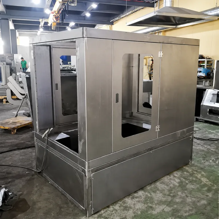
This article addresses side-hinged machine guard doors, enclosure doors, and service doors. A structural opening stop limits maximum swing. It does not automatically hold the door open, reduce opening speed, or support a top-opening cover.
Top-opening covers that require position holding should be evaluated separately. The free-stop versus fixed-angle lid stay guide explains whether an equipment cover should hold anywhere or at defined positions.
Define the Required Service Angle and Maximum Safe Angle
Do not begin by selecting a stop from a catalog angle. Begin with the maintenance or operating task that the open door must support.
A technician may need to inspect a component, remove a filter, withdraw a motor, connect test equipment, access a terminal block, or replace a module through the opening. Each task can create a different minimum usable door angle.
| Données obligatoires | Project source | Why it is needed |
|---|---|---|
| Minimum service angle | Maintenance procedure, service study, or component-removal path | The door must open far enough for the intended work |
| First unsafe angle | Machine layout and swept-volume review | Identifies the earliest collision, overtravel, pinch, or service-line limit |
| As-built angle tolerance | Door, frame, hinge, stop, shim, coating, and installation tolerances | The actual stop angle will not equal one perfect nominal value |
| Stop overtravel | Bumper compression, bracket deflection, tether extension, or structural compliance | The door may continue moving after initial stop contact |
| Opening speed | Operator study, actuator profile, or Project-Specific operating condition | Higher speed increases kinetic energy at the stop |
| Door-mounted protrusions | Complete door BOM and CAD model | Handles, latches, windows, HMIs, and brackets may define the true swing radius |
| Moving services | Electrical, pneumatic, hydraulic, and grounding design | The stop must act before a cable, hose, or bonding strap reaches its limit |
| Adjacent equipment | Machine-cell and installation-site layout | A clear standalone door may strike another installed machine |
| Hold-open requirement | Operating and maintenance procedure | A separate holder, stay, detent, or retainer may be needed after the stop is reached |
The opening-angle boundary should account for the complete tolerance and deflection range:
θservice,max ≤ θstop,min
θstop,max + θovertravel < θunsafe,min
The minimum actual stop angle must still provide the required service access. The maximum actual stop angle, including tolerance, bumper compression, tether extension, bracket deflection, and other Project-Specific overtravel, must remain below the earliest unsafe condition.
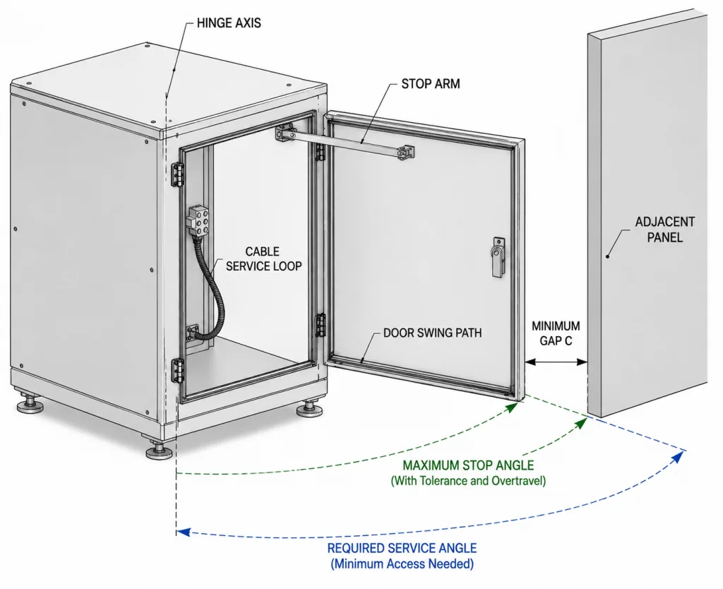
There is no universal correct opening angle for every machine door. A compact filter-access door and a wide robot-cell guard may require different limits even when they use similar hinges.
Map the Complete Door Swing Envelope
The visible door edge is not always the feature that controls clearance. The farthest moving point may be a pull handle, latch housing, interlock actuator, observation-window frame, cable guide, door reinforcement, or component mounted on the inner face.
Build the swing envelope from the functional hinge axis to every significant moving feature. Review the complete path from closed to fully stopped rather than checking only the final position.
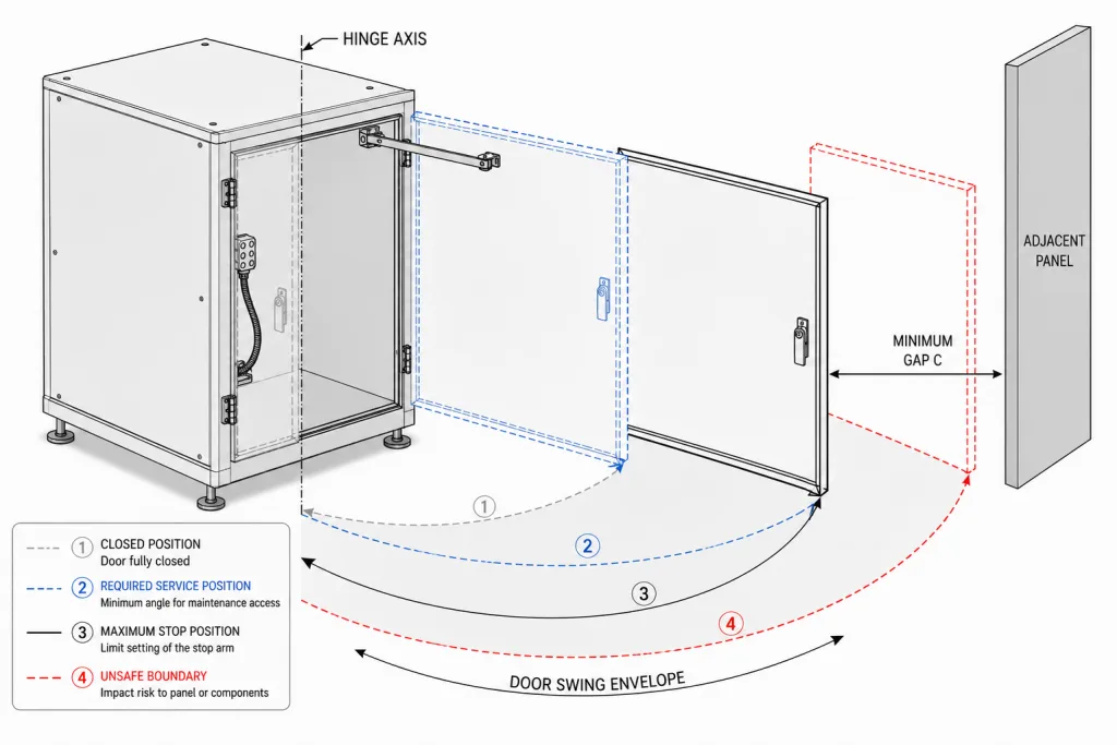
- Establish the functional hinge axis. Use the pin or barrel centerline rather than the outside edge of the hinge leaf.
- Include the complete door thickness. Inner frames, insulation, guards, and protruding hardware may sweep behind the nominal panel plane.
- Include the farthest external feature. Check handles, latch housings, locks, windows, indicators, and brackets.
- Include moving internal services. A service loop, hose, bonding strap, or cable carrier can extend beyond the rigid door profile during movement.
- Check intermediate angles. A feature may clear at the closed and final-open positions but contact the frame or another part at mid-swing.
- Check simultaneous door movement. Double doors and neighboring access panels may occupy the same space when both are open.
- Check the installed machine cell. Include walls, columns, conveyors, cable trays, bollards, guarding, adjacent machines, aisles, and operator work zones.
Clearance must be based on project geometry, manufacturing tolerances, installation variation, expected frame movement, and the maintenance task. A nominal CAD model alone may not represent the minimum field clearance.
Separate the Stop, Hold-Open, and Damping Functions
Several devices can influence the same door movement, but they do not perform the same engineering function.
| Fonction | Primary job | Do not assume it will |
|---|---|---|
| Opening stop | Prevent rotation beyond a defined maximum angle | Hold the door against gravity, wind, vibration, or operator disturbance |
| Hold-open device | Retain the door at the required service position | Absorb uncontrolled impact unless it has an approved stop rating |
| Amortisseur | Reduce angular velocity or soften the final approach | Provide a final structural travel limit without a separate rated stop |
A door may require all three functions. A damper can reduce approach speed, a reinforced stop can define maximum travel, and a separate retainer can hold the open door against airflow, wind, machine vibration, or an inclined installation.
A torque hinge or friction hinge may resist motion and hold position, but it should not be treated as an impact stop unless the supplier confirms the allowable stop angle, static moment, impact condition, rotational inertia, opening speed, cycle exposure, temperature, and mounting orientation.
Choose a Stop Architecture That Matches the Door Behavior
The appropriate stop architecture depends on required angle repeatability, available space, opening speed, environmental exposure, service access, and the stiffness of the door and frame.
| Stop architecture | Useful characteristics | Main engineering risk |
|---|---|---|
| Frame-mounted rigid stop | Repeatable final angle and potentially direct structural load path | High peak load when a moving door strikes a rigid contact |
| Rigid stop with replaceable bumper | Defined angle with reduced noise and local surface damage | A soft bumper does not correct a weak bracket or unsupported door skin |
| Rated limiting arm | Controls travel where direct door-to-frame contact is unavailable | Arm buckling, joint wear, pinch points, side loading, and attachment failure |
| Rated restraint tether or chain | Compact travel limit where rigid contact is impractical | Shock loading, attachment failure, slack variation, snagging, abrasion, and imprecise final angle |
| Damper plus structural stop | Reduces approach speed before a defined structural limit | Damper performance can change with temperature, speed, wear, and orientation |
| Hinge with engineered internal stop | Compact integrated solution where installation space is limited | Internal stop capability may be lower than the real impact, wind, or actuator load |
A restraint tether or chain should be used only when its rated load, attachment points, slack, shock condition, abrasion exposure, environmental condition, and cycle duty have been verified for the actual door assembly.
For large machine guards, outdoor doors, wide flexible panels, or powered doors, a controlled structural stop and Project-Specific dynamic review are normally more appropriate than an unverified flexible restraint.
Place the Stop Contact and Transfer the Load Into Reinforced Structure
The opening stop is not only an angle-setting feature. It is a load-transfer system that begins at the door contact point and ends in the primary machine structure.
Choose a Stable Door Contact Region
- Use reinforced contact areas. Align the stop with an inner door frame, formed return, welded reinforcement, structural tube, or designed mounting pad.
- Avoid unsupported sheet skins. Repeated contact can create dents, coating damage, permanent set, and a changing stop angle.
- Prefer broad, stable contact. Edge or corner contact may slide, chip the coating, or produce an inconsistent final position.
- Control the approach direction. Stop faces should meet without excessive side loading that bends a limiting arm or pushes a bracket out of plane.
- Retain replaceable wear elements. A bumper or wear pad should not walk, split, rotate, or fall out during cycling.
- Account for tolerance. Door, frame, hinge, coating, shim, and installation variation must not change which component contacts first.
- Review wide or flexible doors. One local stop can twist a large panel; two coordinated contact points or additional reinforcement may be required.
Build the Structural Load Path
Door contact pad → door reinforcement → stop face or limiting arm → reinforced bracket → primary machine frame
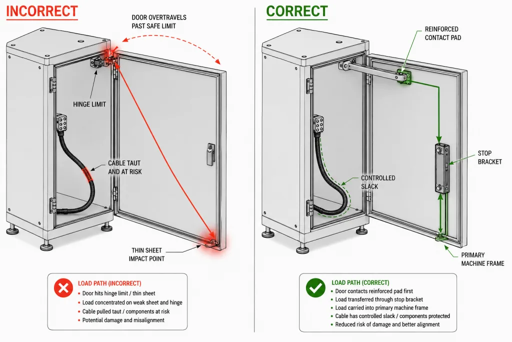
A stop that contacts the middle of an unsupported sheet can dent the door even when the stop bracket and hinge remain intact. A small bracket mounted to a flexible flange can rotate, elongate its holes, crack its weld, or gradually change the opening angle.
The support beneath the door contact and the support beneath the frame-side bracket must both be reviewed. Increasing only the stop-pin diameter does not correct a flexible door return or weak frame wall.
Review Static Stop Demand
For a door rotating about a substantially vertical hinge axis on a level machine, door weight and center of gravity primarily affect hinge support loads and rotational inertia. They do not by themselves create a static opening moment around the vertical axis.
Static stop demand may instead come from wind, an inclined hinge axis or machine base, a spring or torque device, an actuator, an operator-applied force, or another external load.
Mdemand = Σ(Fi × ri)
For one dominant stop contact under a quasi-static condition:
Fstop ≈ Mdemand ÷ rstop
These are general mechanical relationships. They are not a universal stop rating, safety factor, impact multiplier, or production acceptance limit.
Placing a stop farther from the hinge axis can reduce the contact force required to resist the same moment. That location must still align with a sufficiently stiff and reinforced area of the door and frame.
Use the industrial hinge load-capacity guide to verify the hinge and mounting structure under the complete door weight. That calculation does not by itself define the opening-stop load.
Review Dynamic Stop Energy
When a moving door reaches the stop, the relevant condition includes rotational kinetic energy:
Ek = ½Iω²
Où I is the complete door assembly’s rotational inertia about the hinge axis and ω is its angular velocity immediately before stop contact.
Energy alone does not determine peak contact force. Stopping distance, bumper compression, tether extension, bracket and frame stiffness, contact geometry, damping, rebound, and local deformation all affect the result.
Do not apply an undocumented universal impact multiplier. Outdoor doors may also require wind review at the open position, while powered doors require actuator, braking, control-fault, and possible obstruction conditions to be evaluated separately.
ASME Y14.5-2018 (R2024) can be used to define datums, angular dimensions, stop position, and related geometric tolerances on the released drawing. It does not determine the safe opening angle, allowable stop load, cable limit, impact condition, or Project-Specific acceptance criteria.
Set the Stop Before Cables, Hoses, or Grounding Straps Reach Their Limits
A moving cable, hose, cable carrier, or grounding strap must not become the component that stops the door. Connector strain, conductor damage, terminal loosening, hose kinking, and insulation wear may begin before an external failure becomes visible.
| Opening-stop check | Required condition | Failure risk |
|---|---|---|
| First contact | The designed structural stop contacts before the moving service reaches its mechanical limit | The cable, hose, strap, or carrier becomes an unintended restraint |
| Remaining movement allowance | Controlled slack and the Project-Specific bend condition remain at the maximum actual stop angle | Connector tension, hose restriction, conductor fatigue, or snagging |
| Pinch clearance | No contact with the hinge leaf, frame, stop, latch, closing edge, or adjacent equipment | Cut insulation, crushed hose, intermittent faults, or abrasion |
| Anchor stability | Stationary and moving-side anchors do not shift or transfer stop load into connectors and terminals | Loose terminals, damaged strain relief, or changing door resistance |
This section checks the mechanical relationship between the opening stop and the moving services. Detailed cable selection, bend-radius calculation, conductor sizing, shielding, connector placement, strain-relief design, bonding continuity, and long-term flex life belong in a separate hinged-door cable-routing specification.
Protect Adjacent Panels, Equipment, and Service Aisles
A machine door may be clear in the standalone equipment model and still collide after installation. Nearby machines, cable trays, guarding, columns, bollards, walls, conveyors, stairs, and temporary maintenance equipment can reduce the available swing space.
- Will the handle, lock, or HMI strike the next panel before the door edge?
- Can two neighboring doors be opened at the same time?
- Does the open door block an aisle, control station, emergency path, or removable machine module?
- Can the required tool or replacement component pass through the remaining opening?
- Will machine leveling, anchoring, or frame twist reduce nominal clearance?
- Can wind, airflow, floor slope, or vibration move the door away from its intended service position?
- Does the open door create a trapping or pinch region between machine structures?
Where one machine platform is installed in several layouts, define the stop from the permitted installation envelope or release site-specific stop configurations. One maximum angle may not be acceptable at every installation.
Do Not Use the Hinge, Interlock, or Moving Service as an Unrated Stop
A hinge has reached the end of its geometric rotation when a leaf, barrel, pin feature, frame, or internal hinge component makes contact. This does not automatically prove that the hinge can absorb the resulting static, impact, wind, or powered-door load.
Supplier Confirmation Required: Before an internal hinge feature is treated as the opening stop, confirm the hinge model, stop angle, allowable static moment, impact condition, rotational inertia, opening speed, cycle requirement, temperature, mounting orientation, and acceptance criteria.
The following components should not become accidental opening stops:
- Hinge leaf or barrel contact not covered by a documented stop rating
- Hinge pin-retention feature
- Safety-interlock actuator or switch body
- Latch linkage or strike
- Electrical cable, hose, cable carrier, connector, or grounding strap
- Door handle contacting an adjacent panel
- Window frame, gasket, label plate, or cosmetic panel edge
An interlock review in this article covers only mechanical clearance and contact. It does not validate the safety circuit, guard-locking function, diagnostic coverage, or required functional-safety performance.
Validate Machine Door Opening Stops on the Complete Assembly
The stop must be checked on a production-intent or representative door assembly. A stop that works on a light unfinished panel may behave differently after the window, handle, latch, HMI, wiring, insulation, guard, and internal reinforcement are installed.
- Complete the opening system. Install the representative door, hinge mounting, stop, bumper or tether, door hardware, moving services, and neighboring structure.
- Perform a slow controlled sweep. Confirm that the designed stop is the first prohibited-travel component to make contact.
- Measure the actual stop angle. Record the angle from defined machine-frame and door datums, not only from a catalog value.
- Check the complete swing envelope. Confirm service access, cable allowance, pinch clearance, and distance to adjacent structures at intermediate and final angles.
- Apply the Project-Specific opening condition. Include representative manual speed, powered movement, wind, airflow, slope, or another applicable condition.
- Repeat the required operating exposure. Recheck angle, contact sequence, bracket position, reinforcement, wear elements, moving services, and adjacent clearance after the defined cycles or events.
| Stop-specific evidence | Ce qu'il faut enregistrer |
|---|---|
| Actual stop angle | Initial angle, datum method, tolerance, and post-test angle |
| First-contact sequence | Which surfaces contact first during slow and representative-speed opening |
| Stop load condition | Door inertia, opening speed, external force, wind, actuator, slope, and test orientation where applicable |
| Moving-service clearance | Remaining allowance, pinch clearance, abrasion, and anchor stability |
| Adjacent clearance | Minimum distance to panels, handles, walls, equipment, and service paths |
| Structural condition | Contact pad, bumper, limiting arm or tether, bracket, fasteners or welds, reinforcement, and primary frame |
After the stop angle and structural load path are defined, use the machine door hinge assembly validation guide to verify the complete loaded door, baseline geometry, operating exposure, and post-test repeatability before production release.
The hinge attachment method should also be resolved before final validation. Use the weld-on versus bolt-on hinge guide where the mounting architecture remains open.
Read Opening-Stop Failure Symptoms Correctly
| Symptôme observé | Review first | Do not assume |
|---|---|---|
| Hinge leaf bends after the door is opened hard | Missing stop, first-contact sequence, opening speed, and structural load path | A larger hinge alone will solve uncontrolled overtravel |
| Cable or grounding strap becomes taut before stop contact | Stop angle, route, remaining movement allowance, and anchor positions | The moving service can safely act as a secondary restraint |
| Stop bracket gradually changes angle | Bracket stiffness, frame support, fasteners or welds, and dynamic condition | The original angle was simply measured incorrectly |
| Door rebounds strongly from the stop | Opening speed, inertia, bumper stiffness, stopping distance, and damping | A softer bumper alone will always correct the system |
| Bumper splits or moves out of position | Retention, contact area, shear loading, temperature, and compression condition | The bumper is only a cosmetic wear part |
| Door strikes the next panel after installation | Site layout, leveling, installation tolerance, protruding hardware, and actual stop angle | The standalone machine CAD provided enough clearance evidence |
| Interlock actuator shows impact marks | First-contact sequence, door sag, actuator position, and excessive travel | The interlock switch can act as a mechanical opening stop |
| Thin door skin dents at the contact point | Contact location, reinforcement, contact area, and peak load | The design is correct because the stop bracket remains intact |
Composite Engineering Scenario: A Side-Hinged Machine Service Door
Il s'agit d'un scénario technique fictif élaboré afin d'expliquer la logique de sélection. Il ne s'agit ni d'un dossier de projet client ni d'un rapport d'essai de produit.
Consider a tall service door on an automated machine. The door includes a viewing panel, external pull handle, internal interlock actuator, grounding strap, and a cable leading to a door-mounted control device. The machine is installed beside another enclosure with a narrow service aisle.
The initial design allows the door to rotate until the hinge leaves approach their geometric limit. At that position, the handle nearly contacts the neighboring enclosure, and the grounding strap becomes taut. A small rubber bumper is attached to the outer door skin without reinforcement behind the contact area.
The maintenance review shows that the service task requires less opening travel than the original geometry allows. Engineering defines the maximum actual stop range between the required service angle and the first unsafe condition, including manufacturing tolerance and bumper compression.
The revised stop contacts a reinforced inner door frame and transfers load through a supported bracket into the primary machine structure. The cable and grounding routes retain controlled movement allowance at the maximum actual stop angle.
A separate door holder retains the open door during service. It is not used as the primary impact stop. Because the stop bracket, contact region, cable route, and final angle changed, the production-intent assembly is rechecked for first-contact sequence, service access, moving-service clearance, adjacent clearance, and repeated opening before approval.
Machine Door Opening Stop Design Checklist
- The minimum service angle comes from the actual maintenance or operating task.
- The first unsafe angle includes hinge interference, moving-service limits, panel collision, and aisle restrictions.
- The minimum and maximum actual stop angles include manufacturing and installation tolerances.
- Bumper compression, tether extension, bracket deflection, and other overtravel remain below the unsafe-angle boundary.
- The complete swing envelope includes handles, latches, windows, HMIs, brackets, cables, and inner-door hardware.
- The stop, hold-open, and damping functions are assigned to the correct components.
- The selected stop architecture is suitable for the door speed, environment, space, and required angle repeatability.
- The stop contact aligns with reinforced door structure rather than unsupported sheet metal.
- The stop load transfers through a supported bracket into the primary machine frame.
- The stop contacts before a hinge feature, cable, hose, carrier, grounding strap, interlock, or adjacent panel reaches its limit.
- Any tether, chain, internal hinge stop, damper, or bumper has Project-Specific rating or supplier evidence.
- Door inertia, opening speed, wind, slope, actuator force, and other external loads are reviewed where applicable.
- The complete production-intent assembly is used for final stop validation.
- First-contact sequence and actual stop angle are recorded before and after the required operating exposure.
- Clearance is rechecked after machine leveling or anchoring where frame twist can affect the opening geometry.
A preliminary recommendation identifies a possible stop architecture. Engineering review confirms the proposed angle, contact location, load path, and operating condition. Sample approval confirms the representative assembly. Production approval additionally requires released drawings, controlled mounting processes, inspection criteria, and change control.
Questions fréquemment posées
Can the maximum rotation angle of a hinge replace a machine door opening stop?
Not automatically. Maximum hinge rotation describes geometric travel, but it does not prove that the hinge can absorb repeated static, impact, wind, or powered-door stop loads. Use an engineered structural stop unless the hinge supplier confirms the specific stop capability and test condition.
How should the opening angle of a machine door be selected?
Define the maximum angle required by the real maintenance task, then identify the earliest unsafe condition. The minimum actual stop angle must provide the required access, while the maximum actual angle plus bumper compression, bracket deflection, or other overtravel must remain below the first unsafe angle.
Does door weight create the opening-stop load on a side-hinged door?
Not by itself when the door rotates about a substantially vertical axis on a level machine. Door weight mainly affects hinge support loads, while mass distribution affects rotational inertia. Static opening-stop demand may come from wind, an inclined axis, a spring, an actuator, or an applied external force.
Can a grounding strap, cable carrier, or hose be used as a secondary door stop?
No. A moving electrical or fluid service should not become a structural restraint. The designed stop must contact first while the cable, hose, carrier, or bonding strap retains controlled movement allowance and remains clear of pinch and abrasion points.
Does an opening stop also need to hold the machine door open?
Not necessarily. An opening stop defines maximum travel. A hold-open device retains the door at the service position, while a damper reduces movement speed. One device should combine these functions only when its combined load, angle, environment, and cycle duty are explicitly specified and validated.
Is a rubber bumper enough for a heavy machine door stop?
A bumper can reduce noise, surface damage, and impact severity, but it does not replace structural support. The door contact region, stop bracket, mounting interface, reinforcement, and primary frame must still carry the Project-Specific static and dynamic loads.
Should the opening stop be rechecked after machine leveling and anchoring?
Yes when machine support or anchoring can twist the frame or change adjacent clearances. Recheck the actual stop angle, contact sequence, swing envelope, moving-service clearance, and distance to neighboring equipment after installation.
Release the Door Stop From Geometry and Load-Path Evidence
Effective machine door opening stops do more than prevent a door from rotating farther. They define a serviceable maximum angle, keep moving services within their mechanical limits, protect adjacent equipment, and direct the final opening load into reinforced machine structure.
If the door stops only because a hinge reaches its geometric limit, a cable becomes taut, an interlock is struck, or a handle contacts the next panel, the opening system has not demonstrated a controlled production condition.
Submit the Door Opening Data
Send HTAN the complete door drawing, hinge axis, required service angle, first unsafe angle, stop tolerance, expected overtravel, opening speed, stop contact location, door mass distribution, neighboring-equipment layout, moving-service paths, mounting structure, and Project-Specific validation condition.