HTAN is one of the leading manufacturers of industrial hinges, handles and latches in China.


A vibrating equipment cover should not use a draw latch or cam latch simply because one looks stronger. Start with the closed load path. The right family depends on how the latch keeps its retained position, how much gasket pull-down the cover needs, how often the operator opens it, and what happens if the keeper or panel moves under vibration.
Which Latch Family Fits the Cover?
Start With a Draw Latch When
The cover needs adjustable pull-down, visible keeper engagement, sustained gasket seating, or a deliberate closing action that can be checked during maintenance.
Start With a Cam Latch When
Frequent access, quarter-turn operation, compact exterior hardware, or keyed/tool operation matters more—and the selected cam mechanism has a defined way to resist unintended reverse rotation.
If the project has already committed to a draw latch and now needs detailed over-center, keeper, preload, and anti-loosening selection, use the draw latch selection guide for vibration equipment. The decision here comes one step earlier: which latch family is the better fit for the cover?
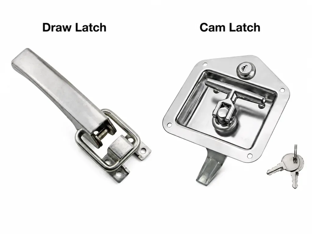
The Closed Position Is a Load Path
Vibration does not act on the handle label. It acts through the cover, latch body, keeper, gasket, fasteners, brackets, and supporting frame. If one part moves, the geometry that originally kept the latch closed can change.
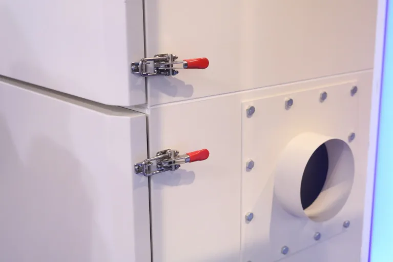
For a draw latch, the useful question is whether the lever-linkage-keeper system reaches a genuinely retained state. A typical toggle arrangement pulls the hook or bail toward the keeper as the lever closes. When the linkage moves past its dead-center condition, the tensile reaction can help keep the lever in the closed direction rather than rotate it open. That geometric margin matters more than the visual fact that the lever is lying flat.
Over-Center State, Not Just Clamp Force
Increasing adjustment on a draw latch can raise pull-down, but excessive adjustment does not automatically increase vibration retention. If the cover, keeper, or mounting flange deflects before the linkage reaches its intended over-center position, the latch may feel tight while the retained geometry is actually poor. A heavily loaded lever can also store elastic energy in the panel or bracket.
That is why “tight” and “retained” are different attributes. The drawing should identify useful adjustment travel, keeper engagement, the final lever position, mounting support, and any safety catch or secondary retention used by the actual model.
A Cam Latch Has a Closed Angle to Retain
A quarter-turn cam latch closes by rotating a cam behind a frame, keeper, or panel edge. The closed angular position may be stabilized by cam geometry, installed preload, operating friction, a detent, spring feature, key or tool lock, press-and-turn action, or another retaining mechanism. Those features are not interchangeable.
A keyed or tool-operated head controls who or what can rotate the latch, but it should not be assumed to provide vibration retention unless the mechanism actually blocks or retains the cam in the closed state. The retention feature has to be identified in the model, not inferred from the handle style.
| Latch Arrangement | Retained State | What Can Change Under Vibration | Drawing / Sample Evidence |
|---|---|---|---|
| Adjustable toggle draw latch | Linkage and keeper remain in the intended closed / over-center relationship | Keeper movement, bracket flex, adjustment movement, lever bounce, loss of hook or bail engagement | Lever position, useful pull-down travel, keeper engagement, adjustment retention, mounting support |
| Plain quarter-turn cam latch | Cam remains at its intended closed angular position | Reverse torque from contact load, loss of friction, keeper shift, grip change, panel movement | Closed cam angle, keeper contact, reverse-rotation path, grip condition, spindle support |
| Cam latch with defined positive retention | Cam is closed and an additional feature resists unintended rotation | Wear or incomplete engagement of detent, lock, spring feature, press-turn feature, or secondary retainer | How retention engages, how it releases, and how engagement is inspected |
A closed handle is only a position. A retained closure is a load path. The first comparison between draw and cam latches should be made from the mechanism that resists movement away from that closed position.
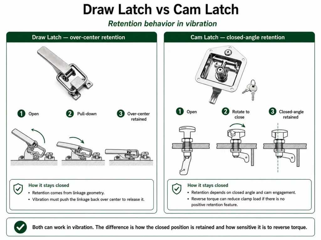
Gasket Load Changes the Mechanism
A gasketed vibration cover adds stored elastic load to the closure. The latch must bring the panel to the required closed stack and then keep the mechanism stable while the gasket pushes back.
On a draw latch, adjustment changes the hook or bail relationship to the keeper. That makes service correction relatively intuitive when a gasket settles or the cover stack changes slightly. The important limit is structural: more pull-down can bend a thin cover flange, rotate a keeper bracket, crush a gasket beyond its intended range, or prevent the linkage from reaching the correct retained state.
On a cam latch, gasket reaction is transmitted through the cam contact back to the spindle. The resulting tendency to rotate the cam depends on the contact force and where that force acts relative to the spindle axis. A simple first-order mechanics view is:
Illustrative cam reaction:
Mrev ≈ Freaction × e⊥
Freaction is the resultant contact or gasket-related reaction transmitted to the cam, and e⊥ is its effective perpendicular offset from the spindle axis. The relationship explains why changing grip, keeper position, gasket stack, or cam geometry can change the reverse torque acting on the closed cam.
This is a simplified mechanics relationship for understanding the load path, not a model-specific cam-latch torque equation or product rating.
Gasket settlement changes the comparison again. A draw latch with accessible adjustment may restore the intended closed stack without changing the latch family. A cam latch may require a different cam offset, grip condition, keeper position, or compression mechanism. If controlled pull-in becomes the primary task, compare the application against the cam latch vs compression latch guide instead of treating every quarter-turn cam as a compression device.
Vibration Adds Inertia to the Cover
A static closure check sees preload and hand-applied forces. An operating machine adds acceleration. The moving cover mass then produces inertial forces that have to travel through the hinge line, latch points, keeper brackets, and frame.
First screening relationship:
Finertia = m × a
This tells you why a heavier cover or higher acceleration can increase the force that the closure system must react. It does not tell you that each latch carries half of that force, or that the local latch load equals m × a.
Local load depends on acceleration direction, hinge and latch locations, cover stiffness, frame stiffness, multiple latch points, and the dynamic response of the assembly. Structural resonance can also change local motion. Use the relationship as a screening concept, not a latch rating formula.
This is where the two latch families can fail differently. A draw latch may keep the lever closed but lose useful pull-down if the keeper bracket moves. A cam latch may keep its spindle fixed in the panel while the changing keeper contact creates a small torque toward the open direction.
There is no universal machine-acceleration threshold at which one family becomes “vibration proof.” The equipment vibration spectrum, cover geometry, retained state, and consequence of opening all matter. A low-amplitude condition near a structural resonance can produce a different local response from a higher base input far from that response.
Access Frequency Changes the Trade-Off
A cover opened during scheduled maintenance can tolerate a slower, more deliberate latch sequence. That favors mechanisms where the operator can see the hook, keeper, lever travel, and adjustment before the machine returns to service.
A cover opened repeatedly during a shift may push the decision toward a quarter-turn cam latch. One-hand operation, a low-profile exterior, gloved access, keyed restriction, or tool operation can reduce service time and keep hardware inside a tighter envelope.
The trade-off is not speed versus safety. It is speed versus how clearly the closed state is established. A fast latch should still give the operator a repeatable stop or engagement condition. If the handle can be left between positions, or if the operator cannot tell whether a detent or lock actually engaged, the faster mechanism may introduce a new failure path.
Frequent access changes human behavior as well as hardware selection. The more often a cover is opened, the more important it becomes that the final closed state is obvious, repeatable, and difficult to leave partially engaged.
Latch Location Changes Cover Behavior
A latch is a point load on a flexible cover. Where that load enters the panel can change both gasket compression and retention. One strong latch near the middle does not guarantee that the corners remain seated. Two latches near the corners do not guarantee equal load if the cover or frame twists.
For a wide cover, spacing the latch points can reduce local panel lift and distribute closing action more evenly. The decision still depends on structure: a latch mounted over a formed return or reinforced edge behaves differently from the same latch mounted in the middle of a broad unsupported sheet.
Two Latches Do Not Automatically Share the Load
If the left keeper is on a stiff welded bracket and the right keeper is on a flexible tab, closing the two latches to the same visible position does not guarantee the same reaction force. Manufacturing tolerance, gasket thickness, coating buildup, cover twist, and adjustment can move load from one latch to the other.
This affects the draw-vs-cam decision because a draw latch may offer visible adjustment at each point, while a cam latch may require grip or keeper geometry to be matched more closely across positions. Neither family fixes an uneven load path by itself.
A practical drawing should therefore show latch quantity, spacing, keeper support, gasket line, hinge line, and the local section under each latch. That is enough to judge whether the family decision is being made on a stable structure without turning this page into a full latch-installation guide.
How Each Family Loses Retention
Draw Latch: Retained Geometry Can Disappear
A draw latch can lose retention without the lever visibly flying open. A keeper bracket can bend, the hook can lose engagement depth, adjustment hardware can move, or the cover can flex enough that the linkage no longer sits as far past its intended dead-center condition. Lever bounce can then become more important because the geometric margin has already been reduced.
Over-tightening can create the same problem from the opposite direction. If closing the lever requires the panel to deform substantially, the assembly stores elastic energy. When vibration changes the panel position, that energy can feed back into the linkage. The cure may be a stiffer keeper or corrected closed stack—not simply more latch adjustment.
Cam Latch: The Closed Angle Can Walk
A plain cam latch may pass a static pull check and still move a few degrees at a time during operation. The cam contact changes as the gasket settles or keeper shifts. If the new reaction produces torque toward open and no positive feature resists that rotation, operating friction becomes the only barrier.
Detents, locks, press-and-turn features, spring-loaded retention, and secondary retainers can change that behavior, but only if they are actually engaged in the installed state. A feature that exists in the catalog but does not fully engage because of grip or mounting tolerance does not provide the intended margin.
The Static Check Passes, Then the Closure Changes
Consider a gasketed cover with a quarter-turn cam latch. On the bench, the handle reaches its stop and the gasket contact looks uniform. During operation, the keeper bracket deflects slightly and the gasket stack settles. The reaction line at the cam shifts, creating a small reverse torque. The cam begins to move away from its original closed angle. Replacing it with a “stronger” cam does not necessarily fix the cause; the retained state and keeper support need correction. This is an illustrative engineering scenario, not a customer project record or product test claim.
The same reasoning should be applied to a draw latch. If the hook, keeper, panel, or adjustment moves, the mechanism that looked secure during assembly may no longer occupy the same retained geometry under vibration.
Draw Latch vs Cam Latch: Selection by Cover Condition
Once the retained state, gasket load, access pattern, and mounting structure are clear, the family decision becomes much simpler.
| Cover Condition | Better Starting Point | Why | What Still Has to Be Proven |
|---|---|---|---|
| Adjustable pull-down with occasional service access | Draw latch | Visible keeper engagement and service adjustment make closed-stack changes easier to manage | Over-center / retained geometry, keeper stiffness, adjustment retention, gasket condition |
| Frequent access with compact quarter-turn operation | Cam latch | Fast operation and keyed/tool options can reduce service effort | Closed angular retention, reverse-rotation resistance, grip, keeper support |
| High sealing demand with controlled pull-in | Draw latch or dedicated compression-latch review | Controlled pull-down may dominate the decision more than handle style | Required gasket compression, panel stiffness, closed stack, service adjustment |
| Large cover with multiple latch points | Either, after load-path review | Spacing and structural stiffness may matter more than family name | Load sharing, local keeper support, corner lift, tolerance across latch points |
| Plain cam with friction-dependent closed position under significant vibration | Reconsider the retention strategy | Reverse torque can move the cam if no positive feature retains the closed angle | Detent/lock/secondary retention engagement and installed vibration behavior |
| Flexible cover or keeper bracket | Neither family should be approved yet | Mounting movement can remove preload or engagement from either latch | Reinforcement, alignment, closed-stack stability |
| Unintended opening has a high consequence | Either family only with defined retained state and appropriate secondary strategy | Failure consequence is more important than convenience | Complete-assembly validation under the project vibration condition |
The table selects a family, not a model. Product-level grip, dimensions, material, finish, operating style, mounting, and retention features still belong to the specific latch drawing and sample.
Validate the Installed Closure Under Vibration
A loose latch on a bench cannot reproduce the cover, gasket, keeper brackets, fasteners, latch spacing, mounting stiffness, and acceleration path of the machine. The final evidence has to come from the installed closure or a representative fixture that reproduces those interfaces.
Before vibration, mark the draw-latch lever and adjustment position or the cam-latch closed angle. Record keeper engagement, cover gap or gasket condition, fastener condition, and the normal effort required to operate the latch. These references make small changes visible after the test.
- Draw latch: inspect lever position, hook or bail engagement, keeper movement, over-center / retained state, adjustment hardware, and any safety feature.
- Cam latch: inspect closed angular position, reverse rotation, grip change, keeper wear, detent or lock engagement, and any reduction in gasket preload.
- Both families: inspect the panel and frame around the latch points. A latch that stays in position while its bracket moves has not demonstrated a stable closure.
- Multiple latches: check whether one point has changed more than the others. Unequal witness marks or gasket gaps can reveal a load-sharing problem that a single-latch inspection misses.
IEC 60068-2-6 provides a standardized method for sinusoidal vibration testing. It does not choose a draw latch or cam latch, set the machine’s vibration severity, or define acceptable latch movement. The equipment specification still has to define the mounting condition, axes, severity, duration, operating state, and pass/fail criteria for the complete cover assembly.
The evidence should answer a simple question: after representative vibration, is the closure still in the same retained state, with the same useful engagement and cover condition needed for service?
Draw Latch vs Cam Latch FAQ
Is a draw latch always better than a cam latch for vibration?
No. A draw latch is often the stronger starting point when adjustable pull-down, visible keeper engagement and gasket seating are priorities, but it still depends on retained linkage geometry, mounting stiffness and adjustment. A cam latch can also work when its closed angular position has suitable retention and the installed assembly passes the required vibration validation.
Can a plain cam latch rotate open under vibration?
It can if the installed contact forces create reverse torque and the closed position depends mainly on friction. Keeper movement, gasket settlement, grip changes and panel flex can alter that torque. A detent, lock, press-and-turn feature, spring retention or secondary retainer may be appropriate depending on the actual mechanism and failure consequence.
Is a keyed cam latch automatically vibration-resistant?
No. A keyed operating head may restrict access, but vibration retention depends on whether the actual mechanism retains or blocks the cam in its closed angular position. Confirm the model’s closed-position retention rather than inferring it from the presence of a key.
Which latch is better for a gasketed vibration cover?
An adjustable draw latch is often easier to tune when the cover needs service-adjustable pull-down. A cam latch can also compress a gasket, but the result depends on cam geometry, grip, keeper position, panel stiffness and the installed gasket stack. If controlled pull-in is the main task, compare the cam latch with a dedicated compression-latch solution.
Can a draw latch still lose retention under vibration?
Yes. Keeper movement, insufficient retained or over-center geometry, lever bounce, adjustment movement, panel flex, loose fasteners or poor hook engagement can reduce retention. The draw latch should be approved as part of the installed latch-and-keeper assembly, not from the family name alone.
After the family decision is clear, use the industrial draw latch range or industrial cam latch range for model-specific geometry and operating options.
Send the Vibration Cover Layout
Provide the cover drawing, gasket or closed-stack condition, latch and keeper mounting sections, latch quantity and spacing, access frequency, preferred operating method, and available vibration information. Those inputs make it possible to compare the two latch families against the actual retained load path before moving to model-level selection.
For a vibration cover, choose the latch family from the retained closed state, gasket load, access pattern, latch location, and consequence of reverse opening. The installed cover-and-keeper assembly—not the words “draw latch” or “cam latch”—is what has to remain stable under vibration.