






Industrial hinges, handles and latches for OEM equipment.
- +86 13720060320


Selecting Stainless Steel Pull Handles for Electrical Cabinets
Stainless steel pull handles for electrical cabinets are easy to approve from a photograph and surprisingly easy to get wrong on the finished door. Two handles can share the same center-to-center mounting dimension yet give the operator very different finger clearance. A handle body can remain perfectly sound while the sheet metal around its feet flexes, the mounting holes leak, or the fasteners interfere with wiring inside the cabinet.
That is why I would not approve a pull handle from overall length and “stainless steel” alone. The real decision is whether the operator, handle, fasteners, door panel, enclosure seal and electrical safety design work as one installed assembly.
This guide is deliberately narrow. It covers a fixed pull handle used to open or close an electrical cabinet door after a separate latch has released it. If the component rotates a cam, drives a rod, restricts access, carries the complete cabinet or operates an electrical control, settle the locking-versus-standard handle decision before continuing.
The six conditions I would settle before model approval
- The part is a pull handle, not a latch, lock, lifting point or control.
- The usable grip and hand-clearance envelope works for the intended operator and gloves.
- The actual door-opening force and pull direction are known.
- The fasteners, panel and reinforcement carry that force without permanent movement.
- The complete material and finish stack suits the exposure and cleaning process.
- Mounting holes, accessible metal and protective bonding are addressed by the cabinet design.
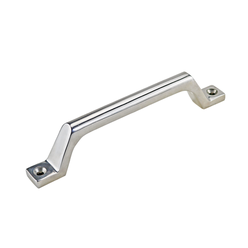
First, name the hardware correctly
Handle, control and knob are not interchangeable terms. Terminology matters because each part creates a different load path and a different safety question.
| Hardware | What the operator does | What the component does | Selection task |
|---|---|---|---|
| Fixed pull handle | Pulls or pushes on a stationary grip | Transfers hand force into the door | Grip, projection, mounting and panel strength |
| Latch | Releases or closes a retaining mechanism | Keeps the door in its closed position | Grip range, keeper engagement, compression and retention |
| Lock | Uses a key, tool or credential | Restricts access | Access control, keying and security level |
| Operating handle | Turns, swings or pulls a mechanism | Actuates a cam, rod, disconnect or other device | Mechanism travel, interlocking and applicable safety requirements |
| Control knob | Rotates or adjusts a control | Changes an electrical or mechanical setting | Control function, indication and human-machine interface |
This page owns the first row only; it does not compare every industrial handle shape or material. If protrusion is the first constraint, settle surface-mount versus recessed handles before comparing individual fixed-pull models.
Grip Dimensions Required on the Drawing
Catalogs naturally lead with overall length or mounting centers because those dimensions are easy to list. The operator, however, uses the space between the handle legs. That usable grip can be shorter than the dimension suggests, especially when the legs slope inward or the end transitions consume part of the opening.
Projection also needs two definitions. The designer needs the maximum distance the handle protrudes from the door because it can become a snag or collision point. The operator needs the clear distance behind the grip because that is where fingers and gloves must fit. Those dimensions are related, but they are not interchangeable.
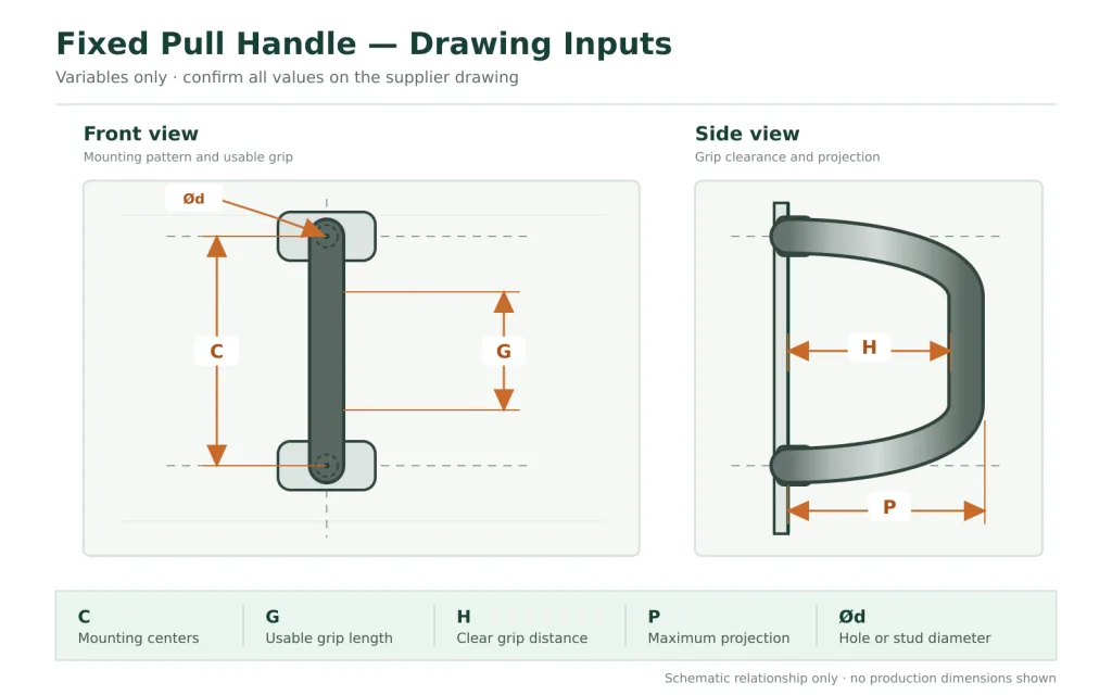
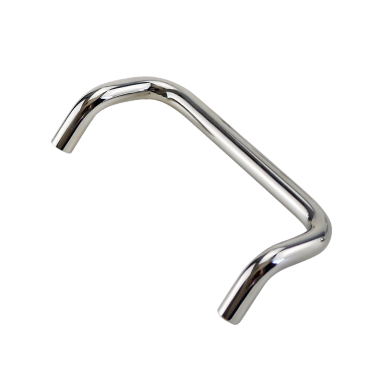
Key drawing inputs for a fixed pull handle: mounting centers C, usable grip length G, clear grip distance H, maximum projection P and mounting diameter Ød. Confirm all values on the model-specific supplier drawing.
| Drawing input | What it controls | Question to answer on the cabinet |
|---|---|---|
| Mounting center-to-center distance | Hole pattern and interchangeability | Do the nominal centers and tolerances match the panel? |
| Usable grip length | One-hand or two-hand access | Is the straight, reachable portion long enough for the intended hand position? |
| Clearance behind the grip | Finger and glove entry | Can the largest intended glove enter without scraping the door? |
| Grip cross-section and edge radius | Contact pressure and comfort | Does the grip concentrate force on a narrow edge? |
| Maximum projection | Aisle, door-swing and packing clearance | Can clothing, carts or adjacent doors strike the handle? |
| Handle position from the door edge | Reach, leverage and door twist | Can the user pull near the latch side without contacting adjacent hardware? |
| Clearance to latch, lock and labels | Safe hand approach | Do knuckles collide with a key, bezel, flange or warning label? |
There is no honest universal “best” clearance for every electrical cabinet. Bare-hand inspection, insulated gloves, chemical-resistant gloves and winter gloves create different envelopes. The quickest useful check is a full-size door or panel mockup with the intended glove, neighboring latch and cabinet flange present. Try the normal approach and the awkward approach an operator will use when standing beside—not directly in front of—the door.
Door-Opening Force and Pull Direction
A large door is not automatically hard to open, and a small sealed door is not automatically easy. Door mass affects hinges and handling, but the pull at the handle can also be governed by gasket compression, latch release, hinge friction, misalignment, seal adhesion, a pressure difference across the panel, cable drag, contamination or ice.
For pull-handle selection, measure the opening force at the intended handle location after the latch has fully released. Record latch-release force separately. Define the remaining conditions: new or aged gasket, expected temperature, clean or contaminated interface, and pull direction. Record the peak force and the force after the seal breaks. If operators may pull before full release, treat that as foreseeable misuse or a separate worst-case condition and address the operating sequence explicitly.
The hand rarely applies a perfectly centered, straight pull. A hurried operator may load one end of the grip, pull upward while opening, or twist the handle to overcome a sticking seal. Supplier load evidence therefore needs a stated direction, fixture, mounting condition and acceptance criterion. “Heavy duty” is a description, not a test method.
My practical rule: never use a cabinet pull handle as a lifting point for the complete enclosure unless that lifting function, load direction, mounting structure and safety factor are explicitly designed and documented.
Panel Reinforcement and the Mounting Load Path
The load path starts at the hand, passes through the grip and feet, crosses the screws or studs, spreads into the door skin and reinforcement, and finally reaches the door frame through the hinges and latch-side structure. A strong handle does not repair a weak link farther downstream.
On thin sheet metal, repeated pulling can dish the panel around a small foot, enlarge a clearance hole or let the handle rock. A large washer may spread clamp load better than a small nut, but it may still be insufficient when the panel itself flexes. A formed return, local doubler, backing plate or other reinforcement may be required. Which one is appropriate depends on the panel material, thickness, unsupported span, opening force and production method.
Resolve the hole patternConfirm centers, hole diameters, positional tolerances and the orientation shown on the latest drawing.
Define the complete stackList the handle foot, gasket if used, painted panel, washers, nuts or inserts, reinforcement and available thread engagement.
Check both sidesVerify front projection and rear clearance to wiring, terminals, insulation, trays and tools used for assembly.
Control retentionSpecify the fastener and anti-loosening method appropriate to the project rather than leaving it to the installer.
Visible screw heads, hidden handle studs, panel-fixed studs and threaded inserts solve different access and service problems. The separate comparison of through-hole versus threaded-stud mounting covers that fastening choice in detail. For this cabinet-level decision, the important point is to specify the entire joint, not merely “two screws.”
Rear clearance deserves particular attention on electrical cabinets. A fastener that fits an empty prototype can conflict with a wire duct, component, insulation barrier or service tool after the panel is populated. The mounting review should use the cabinet’s assembled internal layout, not a blank door drawing.
Tightening torque belongs to the complete joint specification. Too much torque can dish a thin panel, distort a handle foot or over-compress a sealing element; too little can let the feet move and enlarge the holes. Use the fastener supplier’s data and the actual handle-foot, panel, coating and seal stack to establish the production value. Do not copy a universal torque from another cabinet.
For removable through-hardware, decide what happens to each nut and washer during service. Loose conductive hardware must not be allowed to fall into the electrical cabinet. Use captive or retained hardware where the design permits, or define de-energized service, parts accountability and a foreign-object inspection before the cabinet returns to operation.
A useful LS1080 example—and what still needs confirmation
The current HTAN page for the LS1080 equipment door handle gives us a real reference instead of a generic illustration. It identifies model LS1080, stainless steel construction, a mirror finish and size options of 80, 100, 150 and 200 mm. However, the page uses both “opening size” and “hole spacing” for those values. Treat them as family-size references until the controlled drawing confirms which dimension applies to each variant.
What the public product page proves—and what it does not
Currently stated: model family, stainless steel, mirror finish, customization availability and four size references of 80, 100, 150 and 200 mm.
Still required for engineering approval: the meaning of each listed size, exact stainless grade, full dimensional drawing and tolerances, mounting-hole and fastener details, allowable load with test direction and fixture, compatible panel stack, finish specification, corrosion evidence and any model-specific certificate requested by the project.
A product page is a starting point. The controlled drawing, quotation revision and representative sample are the approval evidence.
Stainless Grade, Finish and Mixed-Metal Joints
“Stainless steel handle” is incomplete procurement language. The grade of the grip may be known while the screws, washers, inserts or backing plate remain unspecified. Corrosion can then begin at the least resistant part or at a crevice between parts, even though the visible grip still looks good.
Grade selection should follow the actual exposure. Type 304 is widely used for many indoor industrial applications. Type 316 is commonly considered where chloride exposure or a more aggressive washdown environment makes additional resistance valuable. Neither grade makes the joint immune to deposits, trapped solution, poor finishing, contamination or an incompatible cleaning chemical.
| Application evidence | Material or finish question | What to verify |
|---|---|---|
| Dry indoor cabinet with occasional wiping | Is a declared stainless grade and practical finish sufficient? | Grade, surface condition, fastener materials and cleaning instructions |
| Outdoor cabinet exposed to rain and industrial deposits | Where can water or dirt remain around the feet? | Assembly materials, drainage, crevices, sealing and maintenance access |
| Chloride-bearing atmosphere or cleaning process | Does the grade and surface process match the real concentration, temperature and dwell time? | Exact chemical exposure, supplier material declaration and application-specific corrosion evidence |
| Painted carbon-steel or aluminum door | Can the material interface retain moisture or create a galvanic couple? | Contact area, isolation strategy, coating integrity and fastener stack |
| Frequent abrasive cleaning | Will the finish trap residue or be damaged by the maintenance method? | Approved tools, cleaner compatibility and accessible geometry |
Mirror, brushed and blasted finishes should not be ranked with a one-line rule such as “mirror is always more corrosion resistant” or “brushed always hides scratches.” Surface roughness, direction, finishing quality, embedded contamination and cleaning method all matter. If appearance or cleanability is critical, put the finish requirement on the drawing and approve a physical sample under representative light and cleaning conditions.
Fabrication handling matters too. Carbon-steel particles transferred by shared tools, racks or grinding dust can later appear as rust staining on a stainless surface. If the project controls contamination, that requirement belongs in the manufacturing and finishing specification rather than in a vague promise that the handle is “rustproof.”
Cleaning can be harder on the handle than normal service
The cleaning process needs its own input sheet: chemical name, concentration, temperature, contact time, rinse method, frequency and cleaning tool. Without those details, “washable” and “chemical resistant” are not useful engineering claims.
Look beyond the exposed grip. The narrow space between the handle and door, the underside of each foot, exposed fastener recesses and the edge of a sealing washer can hold residue. A highly polished bar does not make an assembly cleanable when the mounting geometry creates inaccessible crevices.
Also separate cleanability from hygiene certification. Stainless steel is a material choice; it is not evidence that a handle is suitable for a hygienic process or compliant with a food-equipment scheme. If a cabinet sits in a controlled cleaning area, validate the installed geometry and documentation required by that specific project.
Sealing the Handle Mounting Holes
Every hole through a cabinet door creates a possible path for water, dust or cleaning fluid. A stainless handle does not preserve an IP degree of protection or NEMA enclosure Type by itself. That result depends on the installed fasteners, seals, hole quality, coating condition, compression and the enclosure’s required verification method.
A seal beneath the handle foot may help close the penetration, but it can also settle under clamp load or create a wet crevice. Sealant can be useful in a defined joint yet cause inconsistent assembly when its type, bead location and cure are left unspecified. The drawing should show the intended sealing stack and the production plan should control it.
Drilling or retrofitting a handle introduces another boundary: internal electrical clearance. The final fastener length, washer envelope and installation tool must stay clear of conductors, terminals and insulating barriers. Any modification to a populated cabinet belongs under the project’s qualified electrical work and de-energization procedure; a mechanical fit check is not an electrical safety release.
Protective Bonding Is a Cabinet-Level Decision
A stainless steel pull handle is conductive. That fact does not make the handle, its screws or a door hinge a designed protective-bonding path. Paint, oxide, sealing washers, thread coatings, lubricant and joint movement can all change electrical continuity at the mounting interface.
Corrosion control and protective bonding can create opposite requirements at the same joint. A nonconductive washer, bushing or coating used to isolate dissimilar metals or seal a penetration may also interrupt continuity. Design the corrosion barrier and the cabinet’s protective-bonding path separately; do not ask the handle mounting joint to perform both functions by accident.
For machinery electrical equipment, IEC 60204-1 includes protective-bonding requirements. The relevant point here is the boundary: bonding belongs to the electrical equipment and enclosure design. The electrical designer must decide how the door and accessible conductive parts are connected and how continuity is verified. A pull-handle specification cannot make that decision by implication.
Do not turn UL or CE into a generic handle claim
Do not infer certification or conformity status from stainless steel, a catalog photograph or use on an electrical cabinet. If a project requires evidence, request a document that identifies the exact model or assembly, issuing or declaring entity, applicable requirement and scope. If the evidence does not cover the selected handle and revision, leave the claim out.
The same discipline applies to enclosure ratings: the installed cabinet assembly—not the loose handle—must support the claimed result.
What I would inspect first on a prototype
I would start by watching the panel, not staring at the handle. Does the door skin dish inward when the user pulls? Does one foot lift or click? Does the opening force twist the door because the handle is too far from the latch line? These movements reveal a load-path problem before a polished handle shows any visible damage.
Next I would put on the intended glove and open the door from the positions an operator can actually occupy. Knuckle contact with a key cylinder, flange or neighboring control is more useful evidence than a comfortable straight-on grip in an empty workshop.
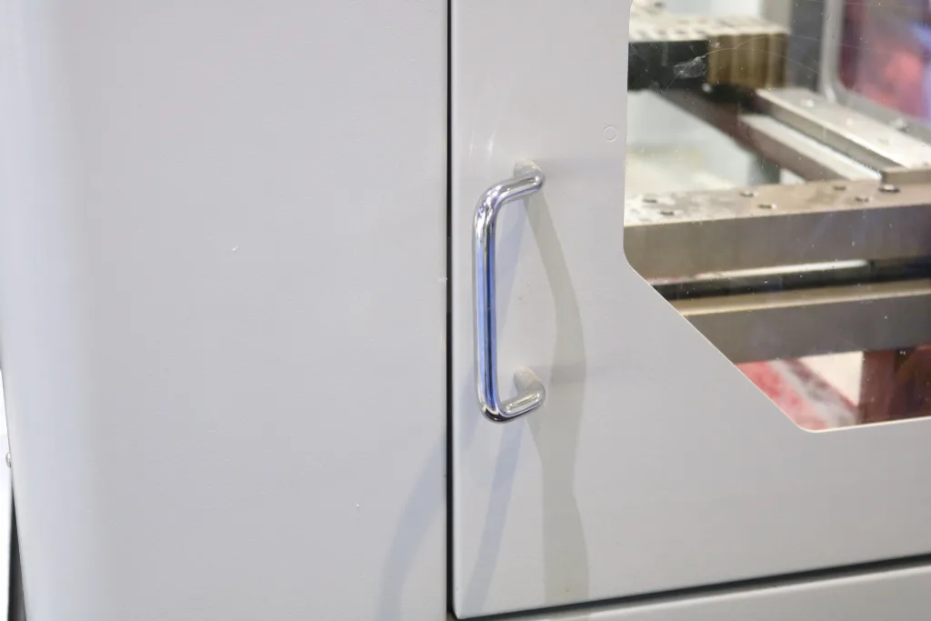
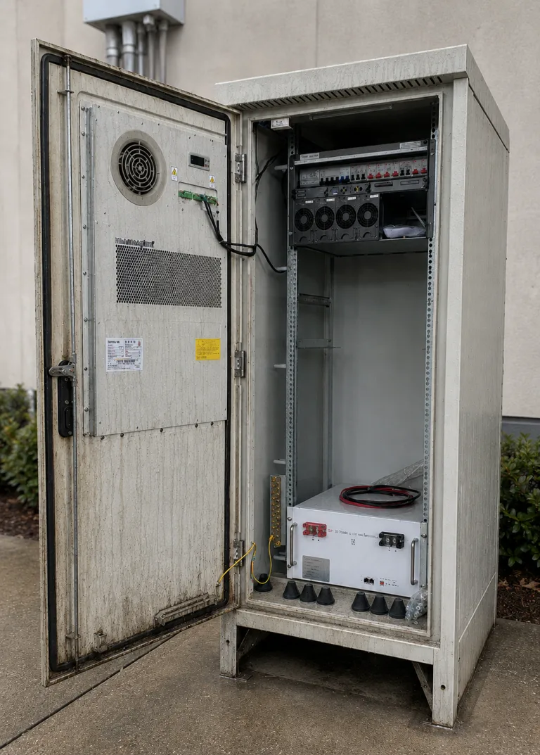
Customer installation photograph of another fixed pull-handle model on an industrial equipment enclosure. The view shows handle position, door edge and surrounding clearance; it does not establish material grade, load capacity, sealing performance or certification.
Finally, I would inspect both sides after repeated operation: witness marks around the feet, coating damage, fastener rotation, ovalizing holes, trapped liquid, wire clearance and movement in any sealing material. None of these checks needs an invented “industry-standard” load. The project defines the duty; the prototype shows whether this assembly can meet it.
Installed-Door Validation
A good sample review uses production-intent parts. That means the specified handle revision, real panel material and thickness, production hole process, actual coating, final fasteners, reinforcement, seals and neighboring hardware. A handle bolted to a thick laboratory plate can pass while the production door fails.
| Approval item | Evidence to record | Release question |
|---|---|---|
| Identity | Supplier, exact model, material declaration, finish and drawing revision | Are purchasing, drawing and sample describing the same part? |
| Grip | Usable length, rear clearance, projection, glove and adjacent-hardware check | Can the intended operator grip and release it without collision? |
| Door-opening duty | Measured condition, pull location, direction, peak and repeated operation | Does the application load stay within documented project limits? |
| Mounting joint | Hole pattern, panel stack, reinforcement, fastener and retention method | Is there no permanent panel movement, loosening or interference? |
| Environment | All assembly materials, finish, exposure and cleaning process | Is the evidence representative of the actual service? |
| Enclosure and electrical boundary | Sealing method, rear clearance, door bonding design and required tests | Does the installed cabinet retain the project’s required safety and enclosure performance? |
| Documentation | Inspection points, approved sample, change control and certificate scope if required | Can production reproduce what was approved? |
Before requesting a model, send the supplier the information that actually changes the answer:
- Cabinet drawing or clear door sketch
- Door material, thickness and reinforcement
- Preferred mounting centers and available footprint
- Required grip and glove clearance
- Front projection and rear clearance limits
- Measured or project-defined opening duty
- Mounting access and preferred fastener method
- Indoor, outdoor, chloride and chemical exposure
- Cleaning chemistry and procedure
- Sealing or enclosure-performance requirement
- Electrical bonding boundary set by the cabinet designer
- Required material, test and certification documents
Send the door conditions before asking for a “heavy-duty” handle
HTAN can review the mounting centers, grip envelope, panel stack, environment and document requirements against an available or customized pull handle. For the fastest useful reply, include a door drawing and photographs of both sides of the proposed mounting area.
FAQ about Stainless Steel Pull Handles for Electrical Cabinets
How do I choose the size of a stainless steel electrical cabinet pull handle?
Start with usable grip length and clearance behind the grip, then check maximum projection, mounting centers, foot size and clearance to the latch or cabinet flange. Overall length alone does not show whether a bare or gloved hand will fit. Confirm the dimensions on the supplier drawing and test the intended operator’s hand approach on a representative door.
Is 304 or 316 stainless steel better for an electrical cabinet pull handle?
Neither grade is universally “best.” Type 304 is common for many indoor industrial cabinets. Type 316 is often considered for chloride-bearing or more aggressive environments. The right answer also depends on finish, fasteners, backing hardware, crevices, surface contamination and cleaning chemistry. Request the exact grade for every relevant part when the environment makes it important.
How much load can an electrical cabinet pull handle carry?
Use a model-specific value that states the load direction, mounting fixture, test method and acceptance criterion. Do not infer capacity from size, stainless steel construction or “heavy-duty” wording. The installed limit may be controlled by the sheet-metal door or fasteners before it is controlled by the handle body.
How can I prevent a pull handle from flexing a thin cabinet door?
First measure the real opening duty and inspect the unsupported panel span. Depending on the design, the joint may need larger load-spreading hardware, a local backing plate, a formed feature or a reinforced mounting zone. Validate the production-intent panel, holes, fasteners and reinforcement together; testing the handle on a thick plate does not approve the door.
Can a stainless steel handle bond or ground the cabinet door?
Do not treat it as the protective-bonding path by default. Paint, seals, coatings and joint movement can make continuity unreliable. The electrical designer must define the door and accessible-metal bonding method under the applicable project requirements and verify it on the cabinet assembly.
Are stainless steel cabinet handles automatically UL or CE compliant?
No such status should be assumed from the material or application. If conformity or certification evidence is required, it must identify the exact product or assembly, applicable requirement and scope. A generic statement or unrelated certificate is not model approval.