HTAN is one of the leading manufacturers of industrial hinges, handles and latches in China.


A machine access door can use a hinge with adequate catalog capacity and still fail during fabrication. The door may fit correctly after tack welding, then bind after the final welds. The latch may align on the welding table but miss after the machine frame is completed. A straight hinge axis can also become curved or offset when separate frame members shrink in different directions.
For welded machine frame door hinges, the hinge is only one part of the structural system. Door mass, center of gravity, frame stiffness, reinforcement, hinge-axis location, fixture design, weld sequence, latch position, and post-weld distortion must work together.
This guide explains how to define that system before fabrication and how to verify it after welding, coating, and final machine assembly. The goal is not simply to weld a hinge onto a frame. The goal is to produce a door that carries its load, rotates freely, returns to the specified closed position, and remains aligned with the latch, seal, or interlock.
Decision Boundary
This article assumes that welded attachment has already been selected. If the project is still deciding between welded and removable attachment, first use the weld-on versus bolt-on hinge decision guide.
The task here is narrower: define and validate the geometry of a welded hinge installation on a machine frame without allowing welding distortion, weak load paths, or inaccurate datums to control the final door position.
Start With the Welded Machine Frame Door Hinge Stack-Up
Do not begin with only a hinge model and a door weight. Begin with a section view through the hinge side of the machine. The section should show every structural layer between the hinge barrel and the primary machine frame.
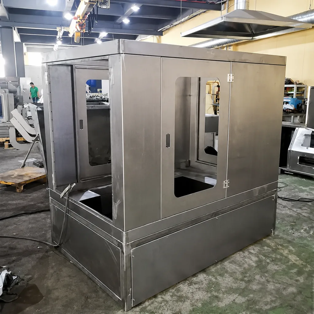
A typical stack-up may include a rectangular tube, formed frame flange, door skin, inner door frame, reinforcement plate, hinge leaf, weld zone, gasket return, guard mesh, or cosmetic cover. The actual combination is project-specific.
The main question is whether the door load enters a structural frame member or stops in a flexible skin. A thick hinge welded to a thin unsupported panel does not create a strong door system. The panel may bend around the weld while the hinge itself remains undamaged.
| Stack-up input | What must be shown | Why it affects alignment |
|---|---|---|
| Primary frame member | Tube, channel, plate, angle, or formed section supporting the hinge | Determines the stiffness and the final load path into the machine |
| Door structure | Skin thickness, inner frame, return flange, window, mesh, and accessories | Controls door deflection and the actual center of gravity |
| Hinge leaf position | Contact surface, weld access, barrel offset, and orientation | Controls the rotation axis and available weld geometry |
| Reinforcement | Backing plate, local tube insert, rib, or formed return | Spreads the concentrated hinge load into a larger structural area |
| Closed interface | Latch, stop, gasket, interlock target, or guard-door overlap | Defines where the door must return after welding and cycling |
| Opening envelope | Required angle and clearance to frame, guarding, cables, and equipment | Prevents the hinge barrel or leaf from creating an interference condition |
The stack-up drawing should also identify which features are structural and which are cosmetic. A painted sheet edge may look convenient for locating the hinge, but it may not be stable enough to serve as the fabrication datum.
Trace the Door Load Into the Structural Machine Frame
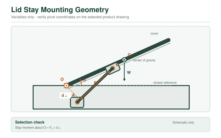
The complete moving-door assembly creates a moment around the hinge axis. A useful first relationship is:
Door moment: M = W × d
W is the gravitational load of the complete moving door, and d is the horizontal distance from the hinge axis to the door assembly’s center of gravity.
This is a general mechanical relationship. It is not a hinge rating, weld-size rule, or final production acceptance criterion.
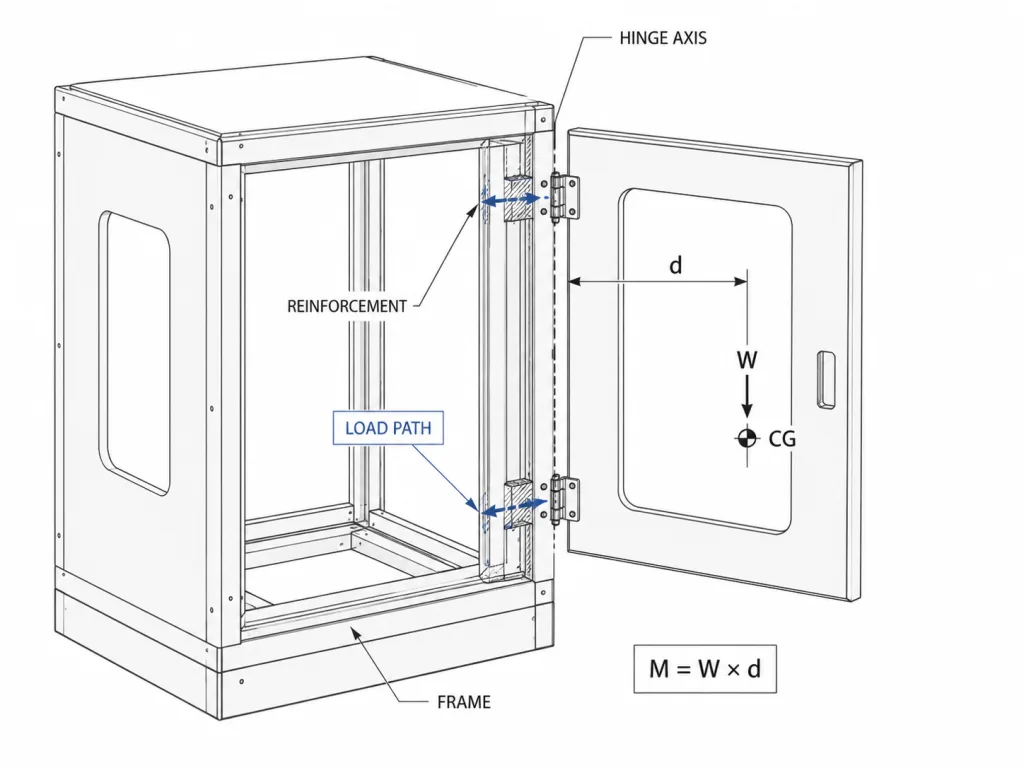
The door moment must travel through the hinge pin, knuckles or barrel, hinge leaves, welds, reinforcement, and frame members. A weak transition anywhere in that chain can cause sag or permanent movement even when the hinge pin is large enough.
Review the following load-path questions:
- Does each hinge leaf connect directly to a structural frame member?
- Does the door-side leaf load an inner frame or only the outer sheet?
- Can the local frame wall bend, twist, or oil-can around the hinge?
- Does the reinforcement end abruptly beside the weld, creating a sharp stiffness transition?
- Does the top hinge region resist the separating force created by the door moment?
- Can vibration move the surrounding frame even if the hinge remains rigid?
The detailed calculations for door mass, lever arm, hinge spacing, radial load, axial load, and safety factors belong in the separate industrial door hinge load-capacity guide. This page uses those results only to define the welded load path.
Define a Measurable Hinge Axis and Datum Scheme
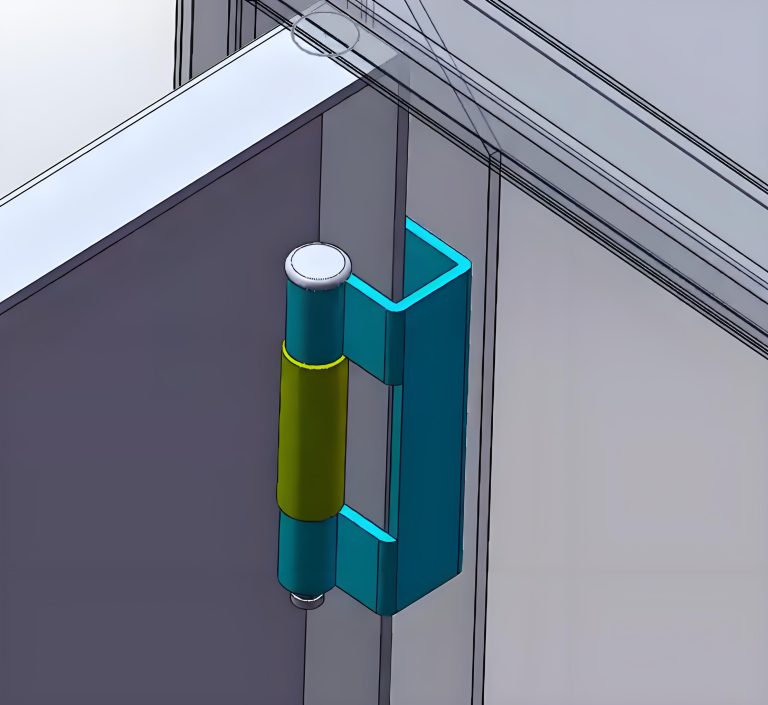
Multiple welded hinges must rotate around one functional axis. Placing each hinge by eye against a nearby sheet edge can produce three individually acceptable locations that do not form one straight axis.
The drawing and fixture should locate the hinge axis from stable structural references. The correct datum scheme depends on how the machine is fabricated and installed, but it should normally connect the hinge axis to the frame opening and the required closed-door position.
| Reference | Possible function | Risk if selected poorly |
|---|---|---|
| Primary structural plane | Locates the hinge axis relative to the machine frame | A flexible or cosmetic surface changes during welding or coating |
| Vertical or horizontal frame datum | Controls hinge-axis orientation | The door gradually rises or falls through its opening travel |
| Door-opening plane | Controls the closed gap and leaf offset | The door fits the hinge but does not sit correctly in the opening |
| Latch or interlock reference | Coordinates the free edge with the closing hardware | The latch or safety switch is forced to absorb hinge-position error |
| Hinge-to-hinge axis reference | Keeps discrete hinge barrels coaxial | The pin binds or the door springs during movement |
Where the hinge design permits, a fixture bar, removable alignment pin, machined locating feature, or common nest can be used to hold the barrels on one axis during tack welding. The fixture must locate the functional rotation axis—not merely the outer edge of each hinge leaf.
ISO 1101:2017 provides the symbol language and interpretation rules for geometrical specifications such as form, orientation, location, and run-out. It can support an unambiguous drawing requirement for the hinge axis and mounting geometry. It does not specify weld size, welding procedure, heat input, filler material, or acceptable weld discontinuities.
Drawing boundary: Do not place a tight hinge-axis tolerance on a feature that the fabrication process cannot measure or control. Define the datum surfaces, measurement method, fixture condition, and inspection stage together.
Control Distortion With the Fixture and Weld Sequence
Welding locally heats the hinge, door, reinforcement, and frame. As the weld metal and surrounding material cool, they contract. If that contraction is unbalanced, it can pull the hinge leaf, rotate the barrel, bow the door edge, or twist the frame opening.
The welding procedure must be developed for the actual materials, joint geometry, thicknesses, hinge design, and production process. A general article should not prescribe a universal bead length, current, filler wire, preheat temperature, or weld size.
The mechanical design and fixture can still reduce distortion risk before the welding parameters are finalized:
- Locate the structural datums. Clamp the machine frame and door from the same references used on the drawing.
- Install the latch-side spacer or inspection gauge. Hold the required closed-door position rather than allowing the hinge to define it accidentally.
- Place all hinges in one common alignment fixture. Confirm pin insertion or free rotation before any final weld.
- Apply controlled tack welds. Recheck the axis, door gap, latch position, and opening movement after tacking.
- Balance heat where the qualified procedure permits. Avoid completing all heat input on one side of the door or one hinge before checking movement.
- Allow the assembly to reach the defined inspection condition. Do not approve alignment only while the frame remains restrained and hot.
- Measure again after fixture release. The fixture can hide residual stress that appears only after unclamping.
| Distortion source | Typical visible result | Design or fabrication control |
|---|---|---|
| Unbalanced welding on one hinge leaf | Barrel rotates toward the weld and the pin begins to bind | Fixture the functional axis and use the qualified sequence |
| Welded reinforcement on only one face of a thin door | Door edge bows toward or away from the frame | Review reinforcement geometry and heat balance before production |
| Frame completed after the hinges are aligned | Machine frame twist changes the door opening | Define when the hinge datum is established in the frame build sequence |
| Hinges welded individually without a common axis fixture | Door moves freely through part of the swing and tightens elsewhere | Locate all barrels from one shared functional axis |
| Assembly accepted while clamped | Door changes position after fixture release | Inspect after cooling and unclamping |
| Weld spatter or heat reaches the moving interface | Rough motion or premature wear | Protect the pin, bushing, seal, and barrel opening during fabrication |
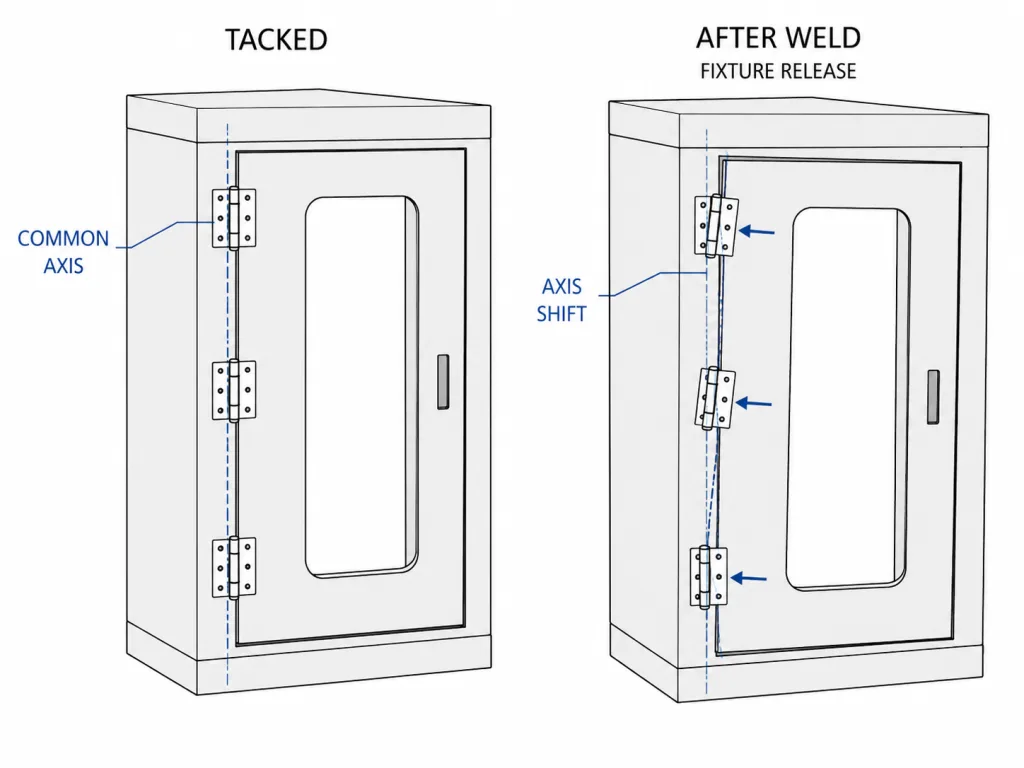
Place the welding return path so that welding current does not use the hinge pin, bushing, or bearing interface as part of the electrical path. Heat-sensitive bushings, seals, lubricants, and removable internal parts also require a hinge-specific installation method.
Place Reinforcement Where the Hinge Load Enters the Frame
Reinforcement is effective only when it transfers load into the surrounding structure. Adding a small plate directly under a hinge may make the weld area thicker while leaving the nearby tube wall, formed flange, or door skin free to bend.
Review the door side and frame side separately.
| Location | What must be resisted | Questions for the drawing review |
|---|---|---|
| Upper frame-side hinge | Local separation, frame-wall bending, and twisting from door moment | Does the reinforcement connect to the primary frame or only to one wall? |
| Lower frame-side hinge | Compression, local bearing, and axis stability | Can the lower structure deform and move the axis under load? |
| Door-side hinge zone | Skin bending, edge twist, and local weld shrinkage | Is there an inner door frame or return flange carrying the load? |
| End of reinforcement | Stiffness transition and cyclic stress concentration | Does the reinforcement terminate directly beside the highest-stress weld? |
| Barrel clearance zone | Full rotation without frame or coating contact | Does reinforcement reduce the intended opening angle? |
No universal reinforcement thickness or length applies to every machine frame. The value depends on the complete door moment, hinge spacing, frame section, steel grade, weld geometry, vibration, impact exposure, and allowable deflection.
The broader relationship between leaf thickness, hinge construction, load, and general durability is covered by the heavy-duty industrial hinge guide. This page remains focused on integrating the selected hinge into a welded frame.
Set the Closed-Door Gap Against the Latch, Seal, or Interlock
A welded hinge becomes difficult to adjust after fabrication. The closed position must therefore be established before the final welds lock the hinge into the frame.
The correct closed position may be controlled by one or more interfaces:
- A latch and keeper that must engage without lifting the door
- A perimeter gasket that requires uniform contact
- A machine-guard overlap that must maintain a specified gap
- An interlock actuator that must enter the switch consistently
- A mechanical stop that prevents the door from loading the latch incorrectly
- A neighboring panel or enclosure surface requiring visual alignment
Do not use the latch to pull a distorted welded door into position unless that function is explicitly part of the design. Excessive closing force can hide hinge-axis error during assembly while transferring the problem into the latch, frame, gasket, or interlock.
For a guard door, test the interlock through the complete opening and closing sequence. Confirm that the switch is not acting as a mechanical door stop and that frame vibration or door sag does not place side load on the actuator.
Alignment check: A door that closes only after the operator lifts, twists, or pushes the free edge is not correctly aligned, even when the latch can eventually be secured.
Recheck Alignment After Frame Completion and Surface Finishing
A door can pass inspection immediately after hinge welding and still fail on the completed machine. Later frame welds, attachment of guarding, lifting, machining, base installation, powder coating, paint buildup, or reassembly can change the final relationship between the hinge, frame, latch, and door opening.
Inspection should follow the actual fabrication sequence rather than occurring only once.
| Inspection stage | Machine-frame-specific checks |
|---|---|
| After hinge tack welding | Common axis, free pin movement, preliminary gaps, latch reference, opening envelope, and fixture seating |
| After final hinge welding | Axis movement, door bow, frame opening, pin insertion, free rotation, and weld-area deformation |
| After the main machine frame is completed | Frame twist, opening squareness, neighboring guard alignment, and interlock position |
| After fixture release and cooling | Residual movement that was hidden by the fixture |
| After coating or paint | Barrel clearance, masked bearing surfaces, door gaps, latch engagement, and coating interference |
| After final machine assembly | Base twist, installed accessories, cables, guard panels, opening restraint, and operating force |
Where the hinge includes removable pins or serviceable components, the inspection should also confirm removal direction, available extraction space, retention, and the ability to reinstall the door without forcing the barrels into alignment.
Diagnose Welded Door Problems by the Symptom
The observed symptom often indicates which part of the welded assembly moved. Avoid replacing the hinge before separating hinge wear from frame distortion, door flex, weld movement, latch error, or coating interference.
| Observed symptom | Likely areas to inspect | Why it may occur |
|---|---|---|
| Door moves freely when partly open but tightens near one angle | Coaxiality of multiple barrels, pin straightness, and frame twist | The hinge axes are offset or angularly misaligned |
| Latch engages only when the free edge is lifted | Door moment, upper hinge region, frame stiffness, and door reinforcement | The loaded door has sagged or the hinge mounting surface has moved |
| Gap is tight at one corner and open at the opposite corner | Door squareness, frame opening, weld shrinkage, and fixture release | The door or frame has become a parallelogram or twisted surface |
| Pin was free after tacking but tight after final welding | Barrel rotation, heat input, weld sequence, spatter, and bushing condition | Final welding shifted the functional axis or damaged the moving interface |
| Crack begins beside the hinge weld | Weld toe, heat-affected zone, reinforcement termination, vibration, and stiffness transition | Cyclic stress is concentrated in a local region |
| Door fits before coating but rubs afterward | Coating thickness, masking, barrel clearance, hinge-side gap, and reassembly | The original clearance did not include the completed finish condition |
| Door position changes after machine anchoring | Base frame, leveling points, anchors, and installed-frame twist | The machine structure moved after the door was originally aligned |
| Interlock actuator shows side wear | Hinge sag, switch position, door stop, and closing path | The switch is compensating for mechanical alignment error |
For welded assemblies, a correction may require more than replacing the hinge. Cutting and rewelding the same hinge onto a distorted or weak frame can reproduce the original failure.
Composite Engineering Scenario: A Welded Automation-Cell Service Door
This is a composite engineering scenario created to explain the selection logic. It is not a customer project record or product test claim.
Consider a tall service door on a welded automation-cell frame. The door carries a viewing panel, handle, latch linkage, and safety-interlock actuator. Three weld-on hinges are proposed along a rectangular-tube frame member.
The first concept places each hinge leaf on the exterior tube wall. The hinge size appears sufficient, but the drawing does not show an internal reinforcement or common hinge-axis datum. Each hinge is positioned from the nearest sheet edge.
During initial assembly, the door fits while the frame remains in the welding fixture. After the surrounding machine base is completed and the frame is unclamped, the latch-side gap changes. The lower portion of the door remains acceptable, but the upper latch no longer enters without pushing the door inward.
The engineering review should not immediately specify a larger hinge. It should first determine whether:
- The hinge axis moved when the main frame welds cooled
- The upper tube wall lacks sufficient local stiffness
- The door inner frame does not carry the viewing-panel mass into the hinge line
- The three hinges were located from separate cosmetic references
- The latch and interlock were installed before the final frame position was verified
A revised concept may use a common hinge-axis fixture, reinforcement tied into the tube structure, a defined closed-door gauge at the latch side, and inspections after both hinge welding and completion of the main frame. The exact hinge model, reinforcement dimensions, weld procedure, tolerances, and acceptance limits remain Project-Specific.
Welded Machine Frame Door Technical Checklist
- The complete moving-door mass includes windows, mesh, handles, latches, cables, and other door-mounted components.
- The center-of-gravity distance from the hinge axis is documented.
- The door-side and frame-side load paths reach structural members.
- The hinge count and spacing are based on the actual door and frame geometry.
- All discrete hinge barrels are located from one measurable functional axis.
- The drawing identifies structural datums rather than relying on cosmetic sheet edges.
- The fixture establishes both hinge-axis location and closed-door position.
- The latch, gasket, stop, or interlock relationship is represented during tack welding.
- The reinforcement connects the hinge load into the surrounding machine structure.
- The weld area has sufficient access for the project welding procedure.
- The pin, bushing, seal, bearing, and lubricant are protected from heat, current, and spatter as required by the hinge design.
- Alignment is checked after tacking, final welding, cooling, and fixture release.
- The door is rechecked after completion of the main frame and surface finishing.
- The latch engages without lifting, twisting, or forcing the free edge.
- The door moves through the required opening angle without binding or frame contact.
- The inspection method and project-specific acceptance limits appear on the released documentation.
A catalog match is a preliminary recommendation. Drawing and load-path review constitute engineering review. A representative welded door assembly is required for sample approval. Production approval should use the released drawing, welding documentation, inspection method, and change-control requirements. These distinctions should remain brief here; a dedicated OEM sourcing-process article is recommended for the broader workflow.
Frequently Asked Questions
Are welded hinges always stronger than bolt-on hinges on machine frames?
No. The complete result depends on the hinge, weld, parent material, reinforcement, frame stiffness, door geometry, vibration, and fabrication quality. Welded attachment removes fastener interfaces but can introduce distortion, residual stress, and difficult field replacement.
How can multiple weld-on hinges be kept on one axis?
Locate the functional barrel or pin axis from common structural datums and hold all hinges in one fixture where the hinge design permits. Check free rotation or pin insertion after tacking, final welding, cooling, and fixture release.
Should the machine door be installed while the hinges are welded?
The correct fixture condition is project-specific. The process must represent the intended hinge axis and closed-door geometry without allowing the door weight, latch force, or fixture restraint to hide distortion. The welding procedure and fixture plan should define the condition clearly.
Can ISO 1101 define the required weld quality?
No. ISO 1101 provides rules for geometrical specifications such as form, orientation, and location. It does not define welding procedure parameters, weld size, filler material, heat input, or weld-defect acceptance.
Why can a welded machine door fit before painting but rub after finishing?
Coating thickness, insufficient barrel clearance, masked-area errors, reassembly variation, or movement during the finishing process can reduce the available gap. The door should be checked in its completed finish and final assembly condition.
Should hinge selection use the bare door weight?
No. Use the complete moving-door assembly, including reinforcement, windows, mesh, handles, latches, interlock hardware, cables, insulation, and any other component that moves with the door.
Release the Welded Door From Measured Geometry, Not Visual Fit
Welded machine frame door hinges should be released only after the complete door load, structural load path, hinge-axis datum, reinforcement, closed-door interface, fixture condition, and inspection stages are tied to the same drawing revision.
A door that appears square while clamped is not sufficient evidence. The completed assembly should remain within its project-specific alignment limits after final welding, cooling, fixture release, completion of the surrounding machine frame, surface finishing, and final installation.
The practical acceptance question is simple: does the completed door rotate freely and return to the required position without forcing the latch, loading the interlock, rubbing the frame, or using the coating and gasket to hide fabrication error?
Submit a Welded Door Interface for Review
Send HTAN the machine-frame section, complete door mass, center-of-gravity position, hinge locations, reinforcement, proposed weld access, datum scheme, latch or interlock position, opening angle, and required post-weld alignment checks.